References/links:
I needed to make some automated measurements that require the output of a two-quadrant power supply. Since the DP832 is the only (working) programmable power supply available at my lab I have put together this circuit that transforms it from a 0 - +30V to a 0 - ±30V power supply.

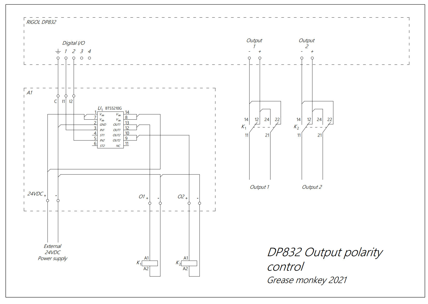
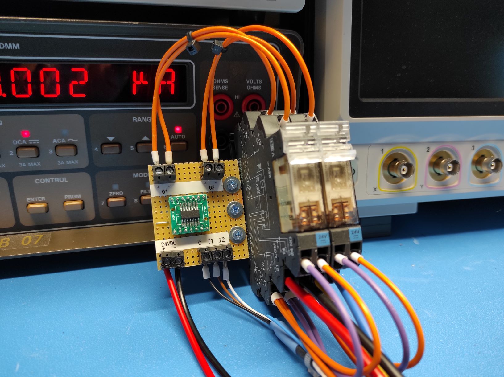
The circuit is pretty straightforward. Digital I/Os 1 and 2 control relays K1 and K2 respectively. The choice of material was from I had available in my lab.
The digital I/Os of the RIGOL DP832
The User's Guide of the DP800 Series does not provide much information about the digital I/Os (page 2-37 of the User's Guide). From measurements I have made when they are used as outputs the voltage level is about 3.2V and they cannot source much current (a few mA maybe). The I/Os don't mind if you short-circuit them though.
So in order to drive a relay you need some amplification. It should be possible to drive a relay throught a small BJT or FET. Since I had the BTS5210G Power Switch handy I didn't bother looking into it any further.
To setup an I/O as an output through LXI you need the following command:
:TRIG:OUT:COND D0,AUTO
This commands sets the trigger condition of I/O 0 to automatic. The output will turn on when it is enabled and off when disabled. The following commands enable and disable the I/O respectively:
:TRIG:OUT:ENAB D0,ON:TRIG:OUT:ENAB D0,OFF
Testing
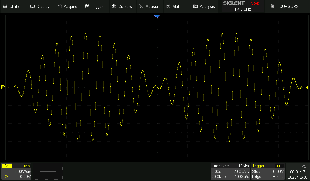
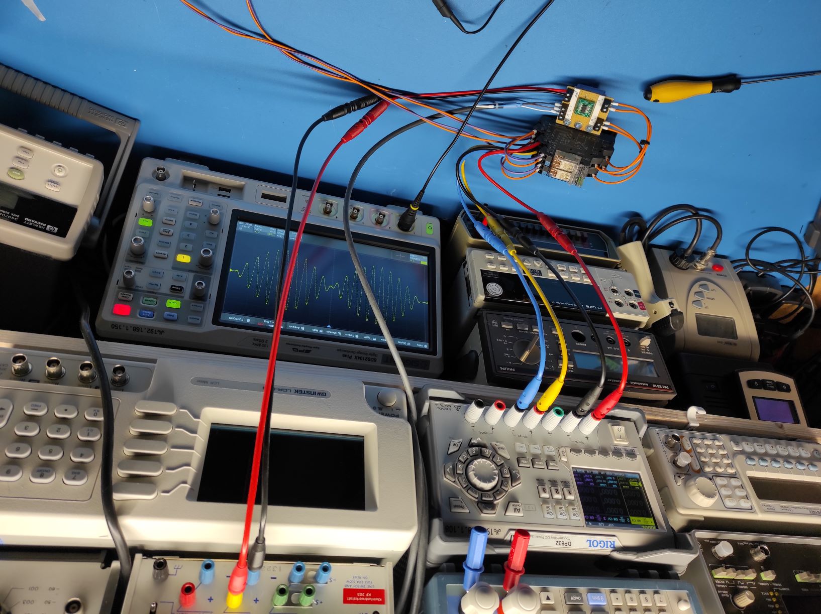
To test the setup I connected the output to my oscilloscope and modified the python code from this post to output negative voltages too. These are the results:


The modified code:
