References/links:
There is an automation circuit that we do often at work. It takes two sensors as inputs and has a relay as output. It also needs a timer and two more relays. The circuit is not complicated enough to justify a small PLC like Siemens LOGO!. Another cost that is rarely considered is that if you add a programmable device you need someone to reprogram it when it needs replacement. Still I thought it would be great if could do it a small custom PCB with a microcontroller. But I wanted to do it right so I decided to use the ISO121x isolators from TI. Not that I needed galvanic isolation but these chips take care of the current draw requirements of IEC 61131-2.
The problem was that they were out of stock and the lead time was about a year(!). So, I thought, what the hell let's do it old-school with discrete components.
About IEC 61131-2
In an industrial environment there is electromagnetic noise. A lot of it. And you don't want your digital inputs activating without a reason. So the digital inputs of industrial devices are low impedance. In other words the amount of power needed to activate an input is well above the levels that could be introduced by random noise.
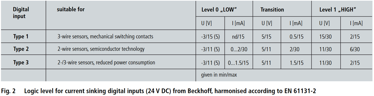
For a more detailed explanation of the standard I suggest you read the application note. It is very informative. The following table (taken from Beckhoff Application Note DK9222-0909-0008) sums up the the IEC 61131-2 levels.
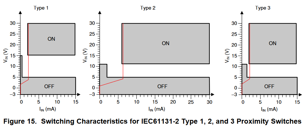
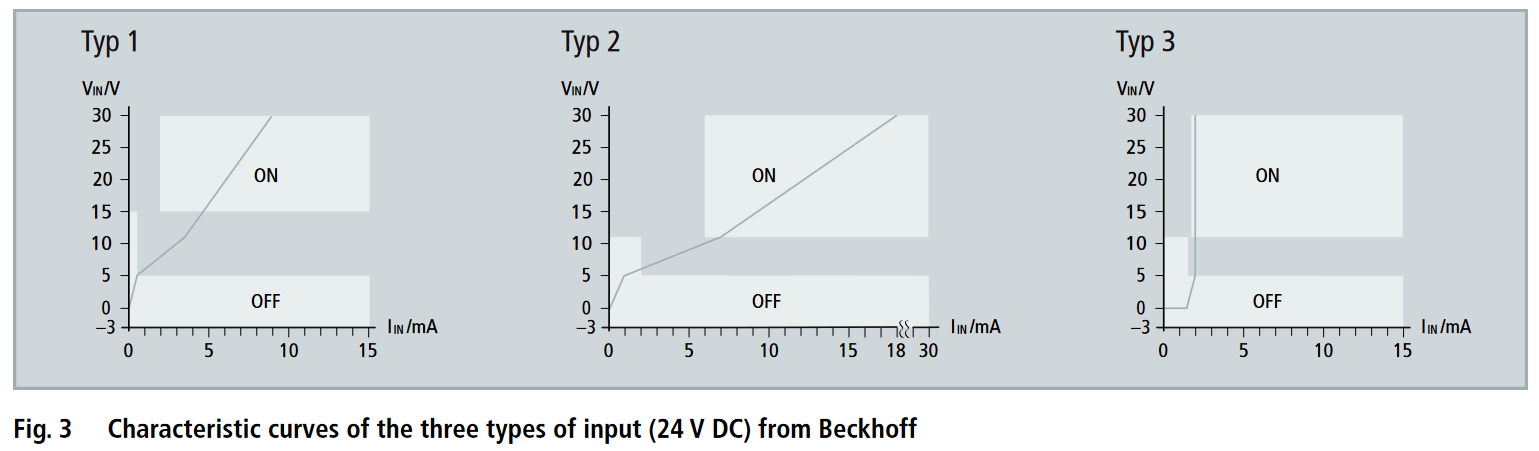
And here are current curves of various types of Beckhoff digital input modules.
My solution
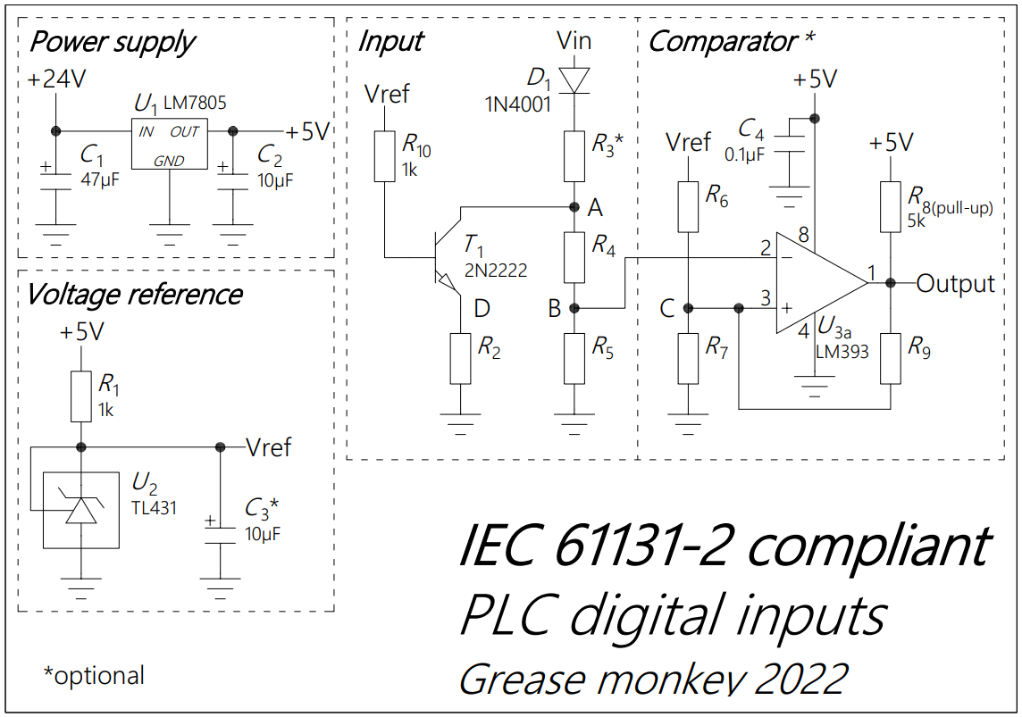
Circuit description
- $U_1$ gives us a regulated 5V supply for the LM393 comparator and the TL431 voltage reference.
- $R_1$ sets the cathode current of the reference: $$I_{R_1} = \frac{5V - V_{ref}}{R_1}$$ to about 2.5mA. The minimum cathode current for the correct operation of the TL431 is 1mA.
- $T_1$ and $R_2$ form a constant current sink. $T_1$ is connected as an emitter follower. The voltage of point $D$ ($V_D$) remains constant at about: $$V_D = V_{ref} - 0.7V$$ $R_2$ is setting the current: $$I_{R_2} = \frac{V_D}{R_2}$$
- $R_3$ lowers the voltage at the collector of $T_1$ and shares some of the thermal load. Since the current remains constant the total power dissipation is: $$P_{tot} = Vin \cdot I$$ and for each component: $$P_{R_3} = I_{R_2}^2 \cdot R_3$$ $$P_{R_2} = I_{R_2}^2 \cdot R_2$$ $$P_{T_1} = P_{tot} - P_{R_2} - P_{R_3}$$ As you can see the current that flows through $R_4$ and $R_5$ is excluded from the calculations. Since we are not concerned with accuracy, a few tens of μA here and there do not matter.
- $R_4$ and $R_5$ form a voltage divider to feed the signal to the comparator. The voltage of point $B$ ($V_B$) is: $$V_B = V_A \cdot \frac{R_5}{R_4+R_5}$$ and $$V_A = V_{in} - I \cdot R_3$$
- Finally $D_1$ is a reverse current protection diode to comply with the -3V limits of the standard.
- The comparator circuit is a classic inverting input comparator with hysteresis. Since the LM393 has an open collector output, it needs a pull-up resistor ($R_8$). The calculation of the thresholds is not difficult but I am trying to cut down on my masochism so I used this calculator to calculate the values.
Optional components
If you are stressed for PCB space, budget or circuit complexity all components marked with an asterisk (*) can be removed and the circuit will work just fine.
$C_3$ is a buffer capacitor for the TL431 reference. Since the load is just the base current of the transistor and it remains stable, removing it will not make a difference.
$R_3$ shares the thermal load with the transistor and lowers the voltage of point A. The circuit will work fine with input voltages up to 30VDC even if you remove it. You can also use a higher voltage/power transistor according to your needs.
Finally you can do away with the comparator if you connect point $B$ to a microcontroller digital input. If you adjust the $R_4 / R_5$ ratio to the schmitt trigger thresholds of the input, it should be possible to match them to the IEC 61131-2 thresholds of your choosing.
Alternately you can connect point $B$ to an ADC input too. Of course you will have to poll the analog input continuously. The speed will be considerably reduced. The voltage thresholds will have to be set in software.
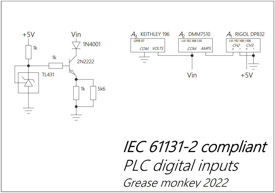
Testing the circuit
To test my idea I constructed the circuit bellow on a breadboard. Since the sensors I plan to connect are 3-wire 24VDC sensors I am going to focus on Type 1 inputs. The input current ($I_{IN}$) is measured by $A_2$. $A_3$ is used to measure $V_{IN}$ but only because my DP832 is out of calibration.
The Python script that records the measurements and plots them can be found here.
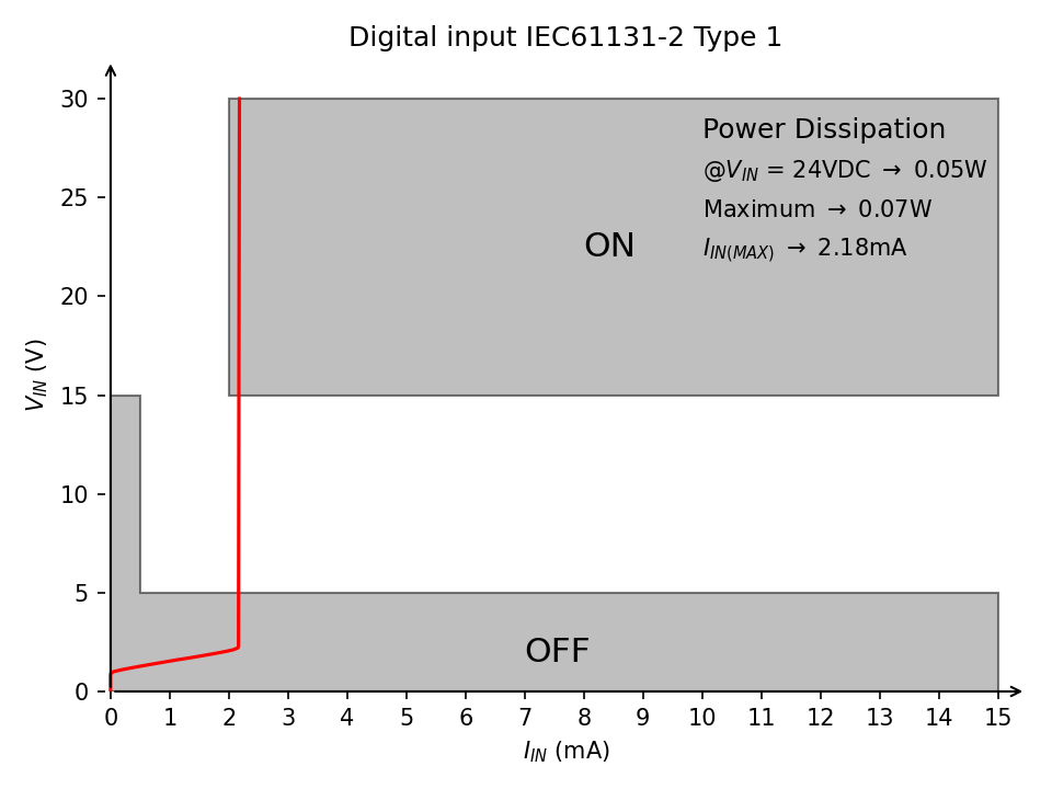
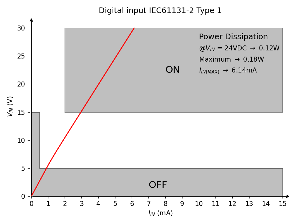
As you can see the power dissipation at 24VDC is just 0.05W. This means that you can cram many digital inputs without worrying about overheating. The switching voltages $V_{IN (ON)}$ and $V_{IN (OFF)}$ will be tested when I construct the final circuit for my project.
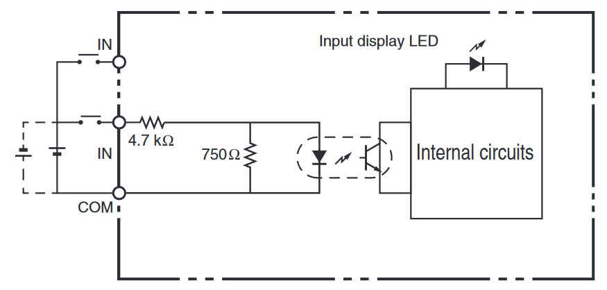
How are the others doing it?
I have some PLCs laying around my lab so I thought it would be interesting to run the same test on them. Most of the PLC input cards I took apart use a variation of the following circuit: