References/links:
This post contains notes on the use of the ATtiny824 micro-controller with the Arduino IDE. I do not go deep in to the inner workings of the micro-controller. It is more like a quick reference guide.
I am using the megaTinyCore by Spence Konde and most of the pictures and code are from there. A big thanks to Spence Konde. Great work!
Pinout
Programming
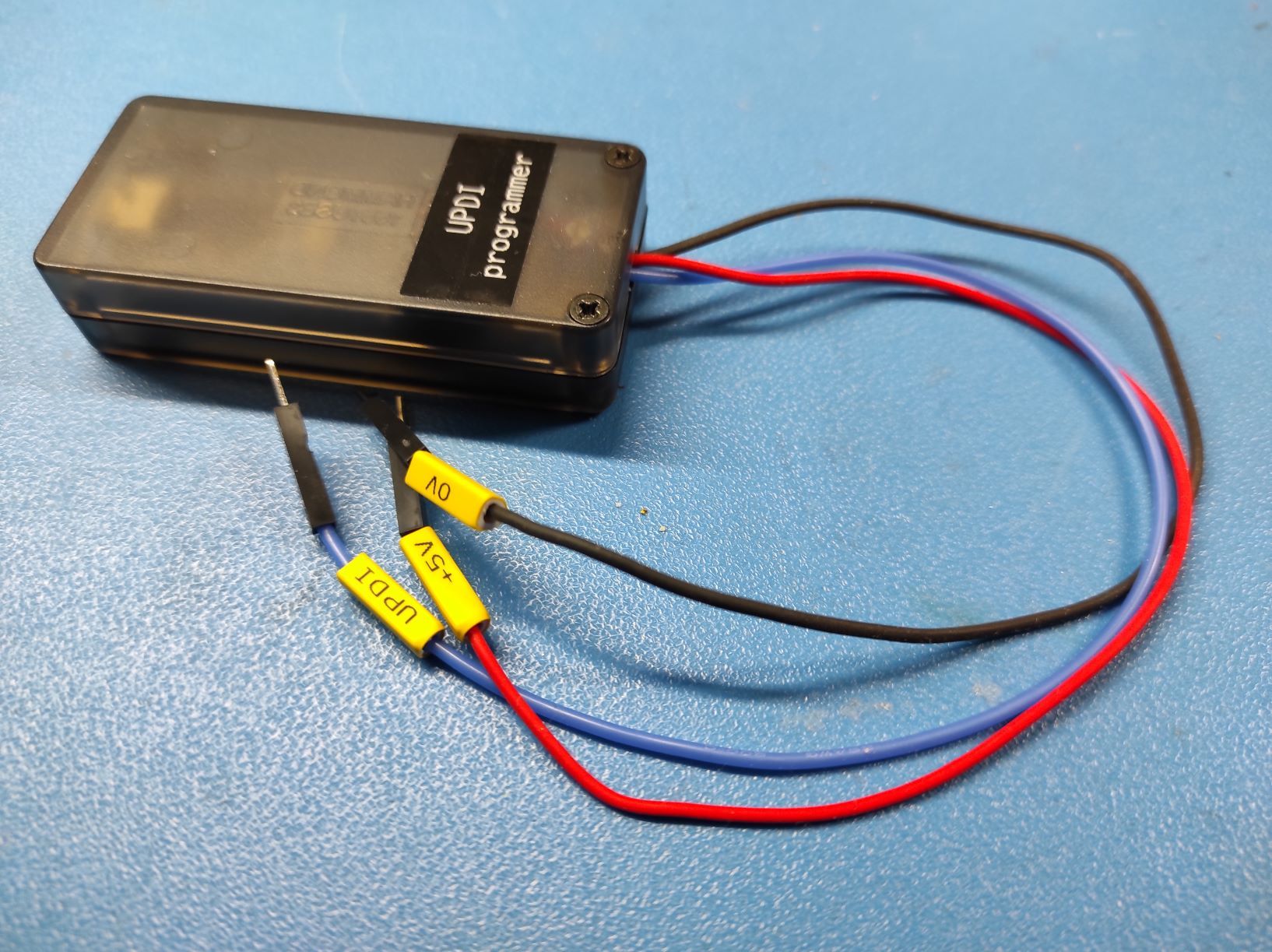
To program the chip you need to make a UPDI programmer. I used the instructions here to make one with an Arduino nano.
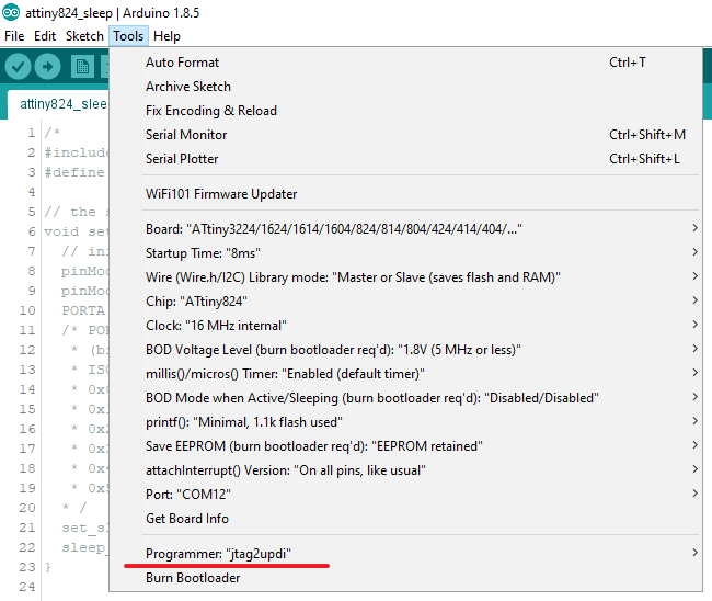
Once you have installed megaTinyCore to the Arduino IDE use these settings and you are good to go:
Code examples
Blink
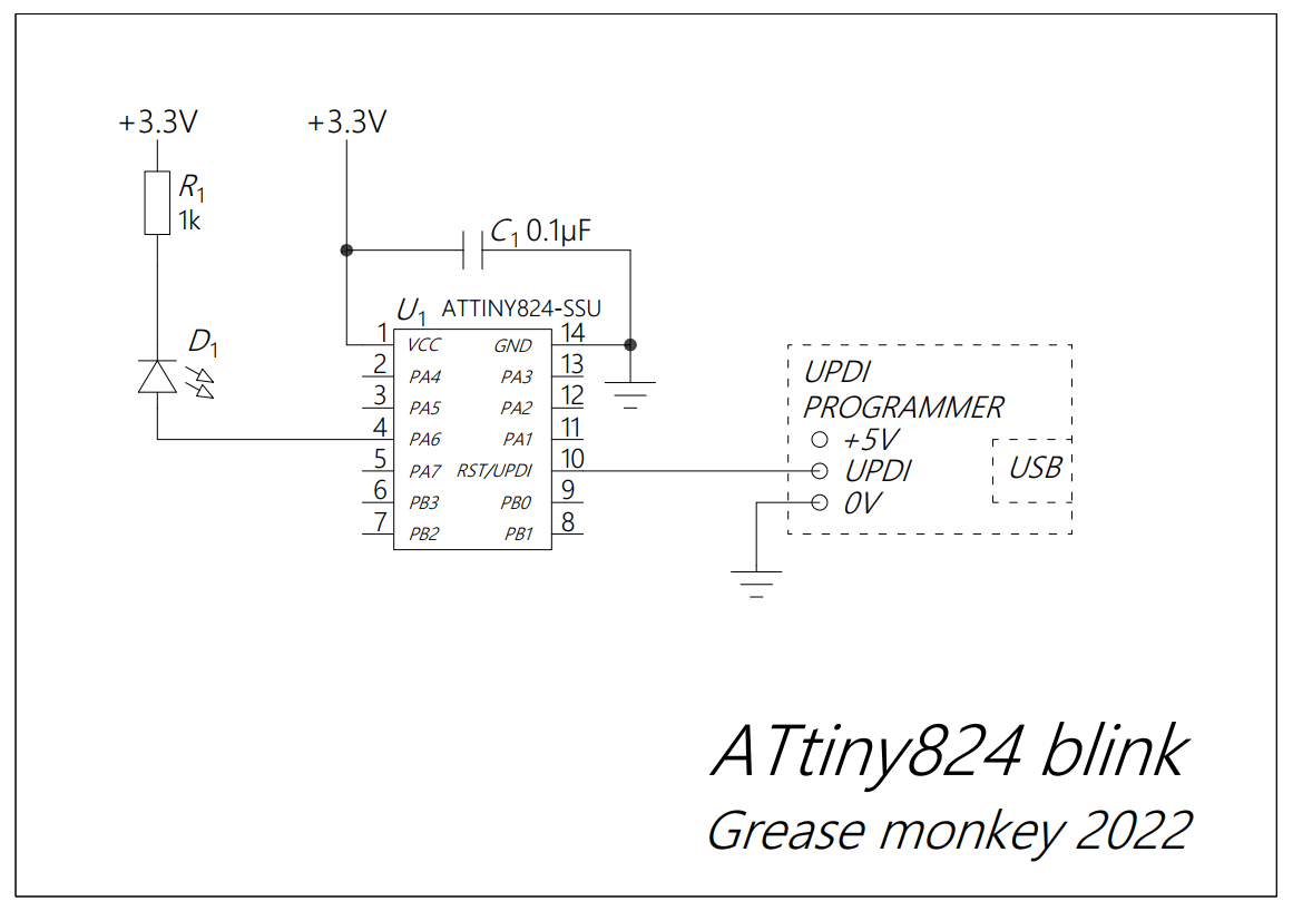
Note: The pins can be address as PIN_Pxn, where x is the port (A or B) and n is the bit number (0-7). E.g. pin 4 (PA6) is PIN_PA6.
Serial port
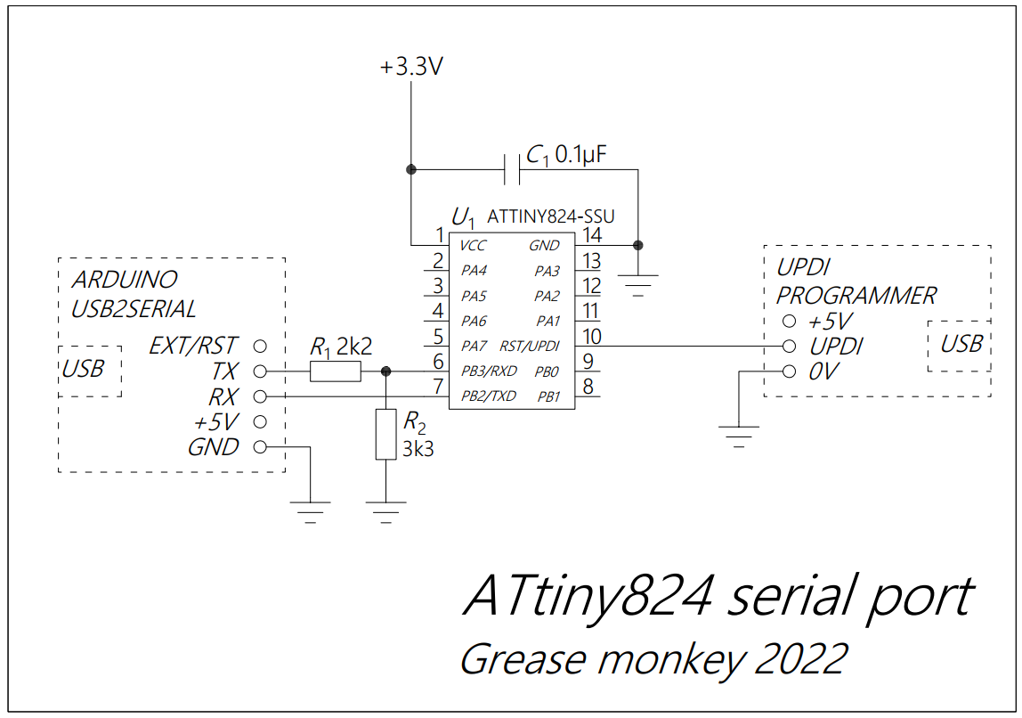
Note: R1 and R2 make a simple level translator (5V to 3.3V).
ADC
Note: More details here:
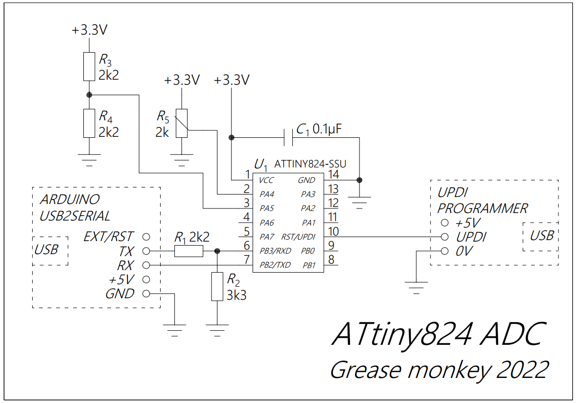
1. Reading at various resolutions with VDD as analog reference:
2. Differential reading between PA4 and PA5 using the internal 2.048V analog reference:
3. Reading VDD
4. Reading the internal temperature
Reading the internal temperature sensor of the ATtiny824. Page 415 of the datasheet. The typical accuracy of the sensor is ±3 °C (page 490 of the datasheet).
Watchdog timer
Note: Read more here.
Just enabling the WDT and resetting it.
Pin interrupts
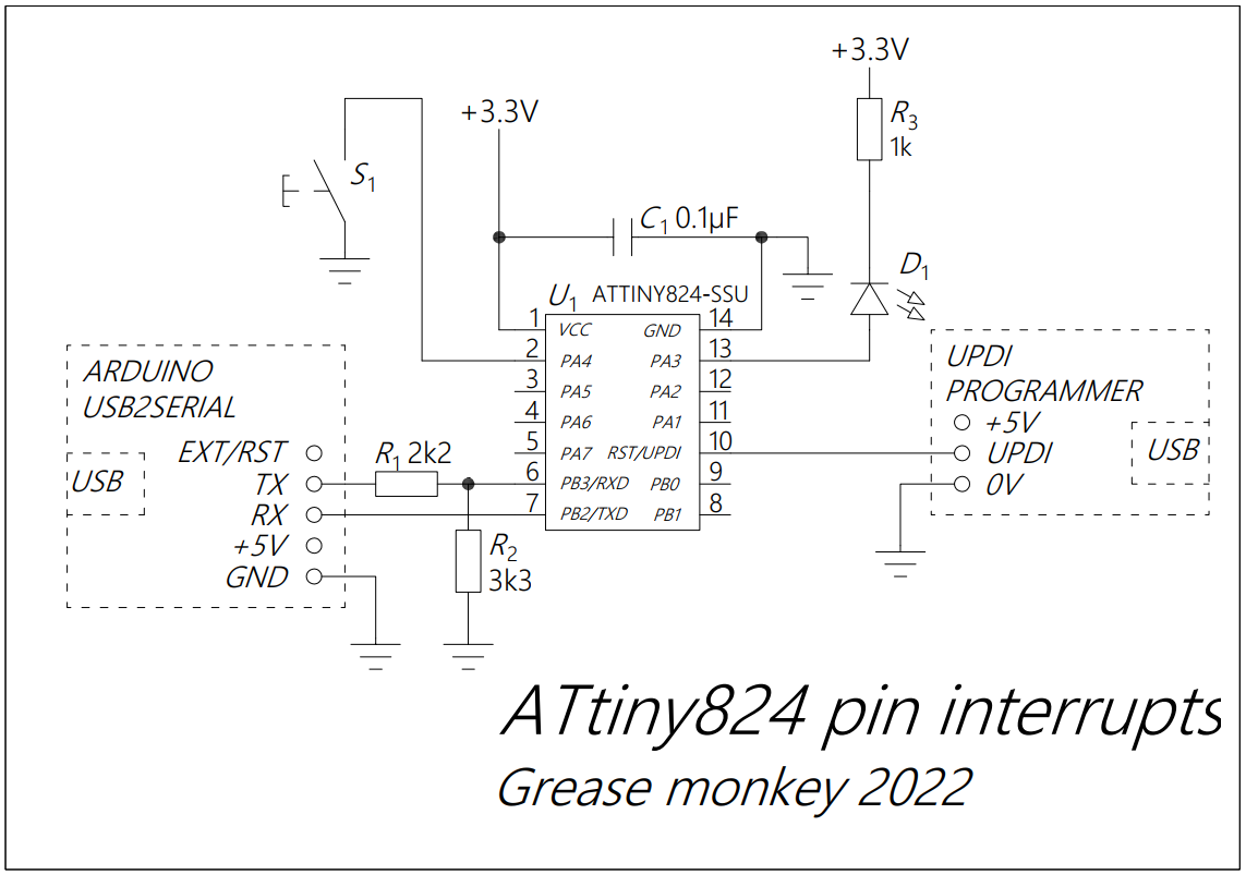
Note: Read more here.
I2C
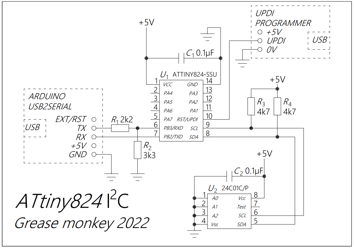
Note: The test sketch is the WriteReadByte.ino from this library. (Copyright © 2012 Julien Le Sech)
1-Wire (kind of...) DHT11 temperature and humidity sensor
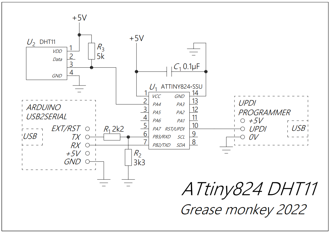
NOTE: Library and example downloaded from microbot.it. Change the pin allocation to PIN_PA4.
To be continued...