References/links:
- EEVBlog thread
- Low level measurements handbook
- LMC662 Datasheet
- The 1GOhm resistor used
- Coax cable for the capacitor
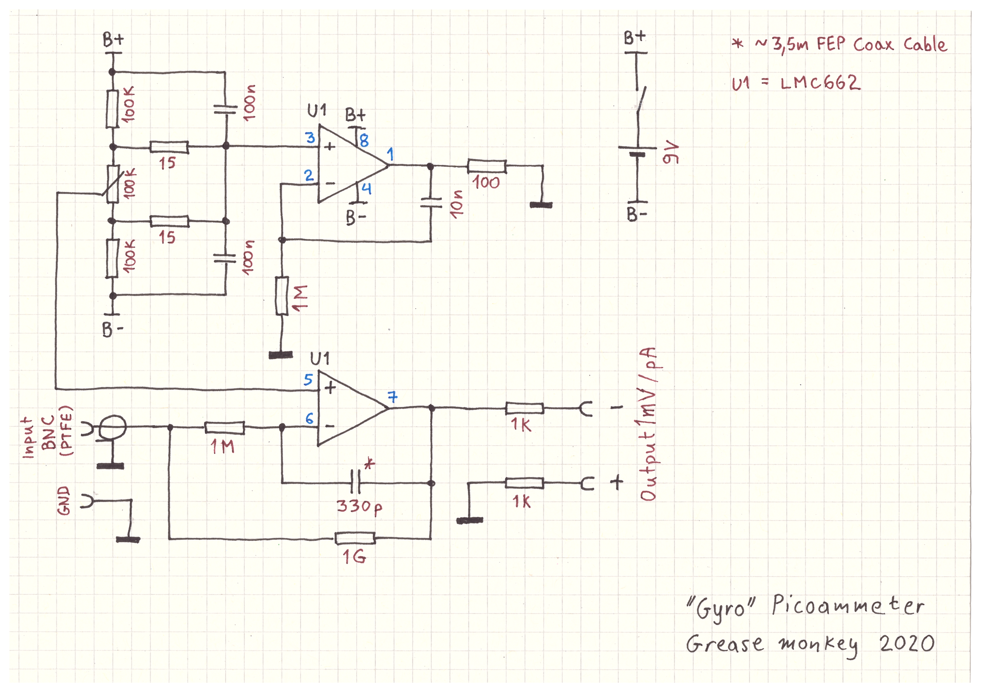
The things I changed from the original design are the capacitor (I used a coax cable) and the output protection (there is none).
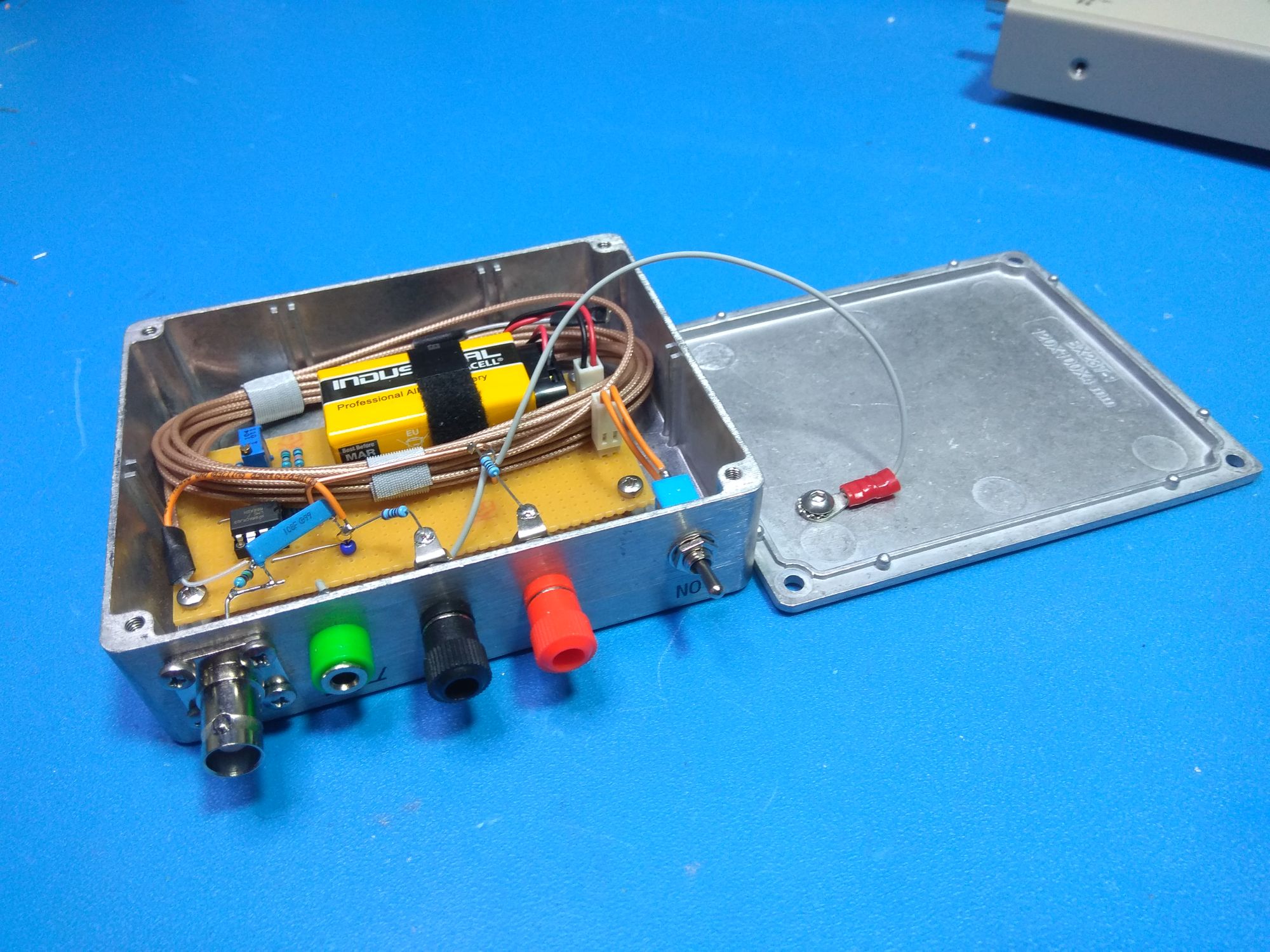
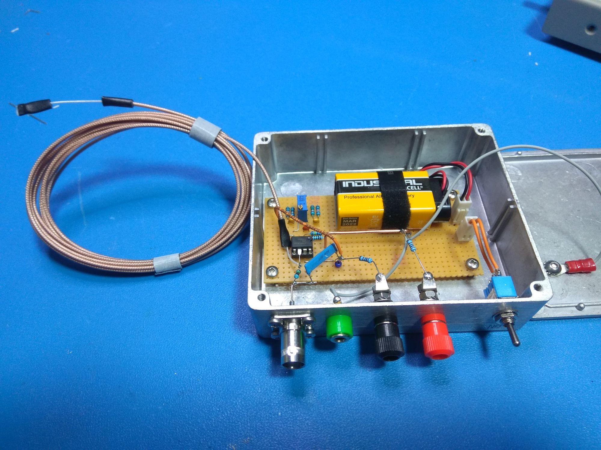
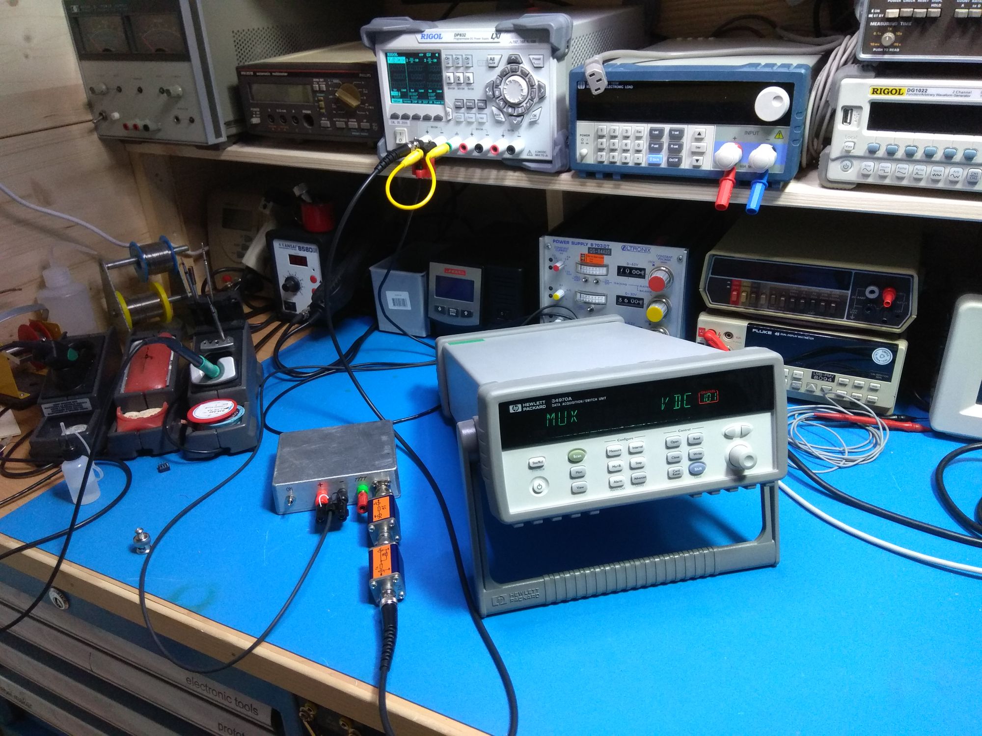
Build photos
Tests
The environmental conditions in my lab are relatively stable. At the time of measurements: 20.5°C, 50%RH. The elevation is 625 m.
In all the tests the picoammeter was warmed up for at least 30 minutes.
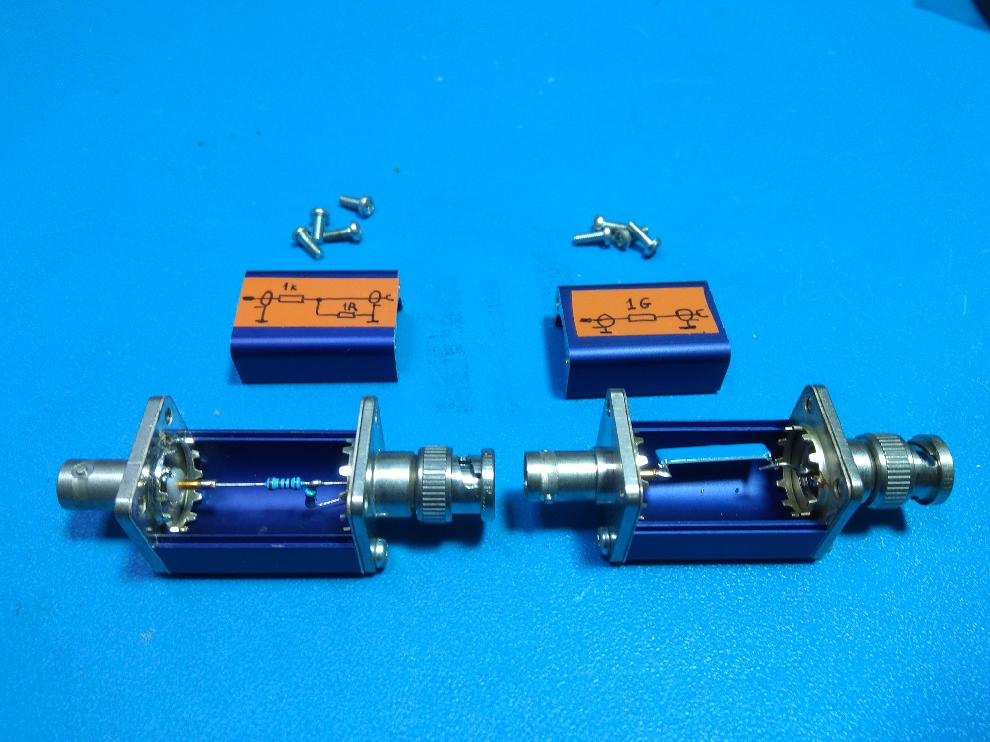
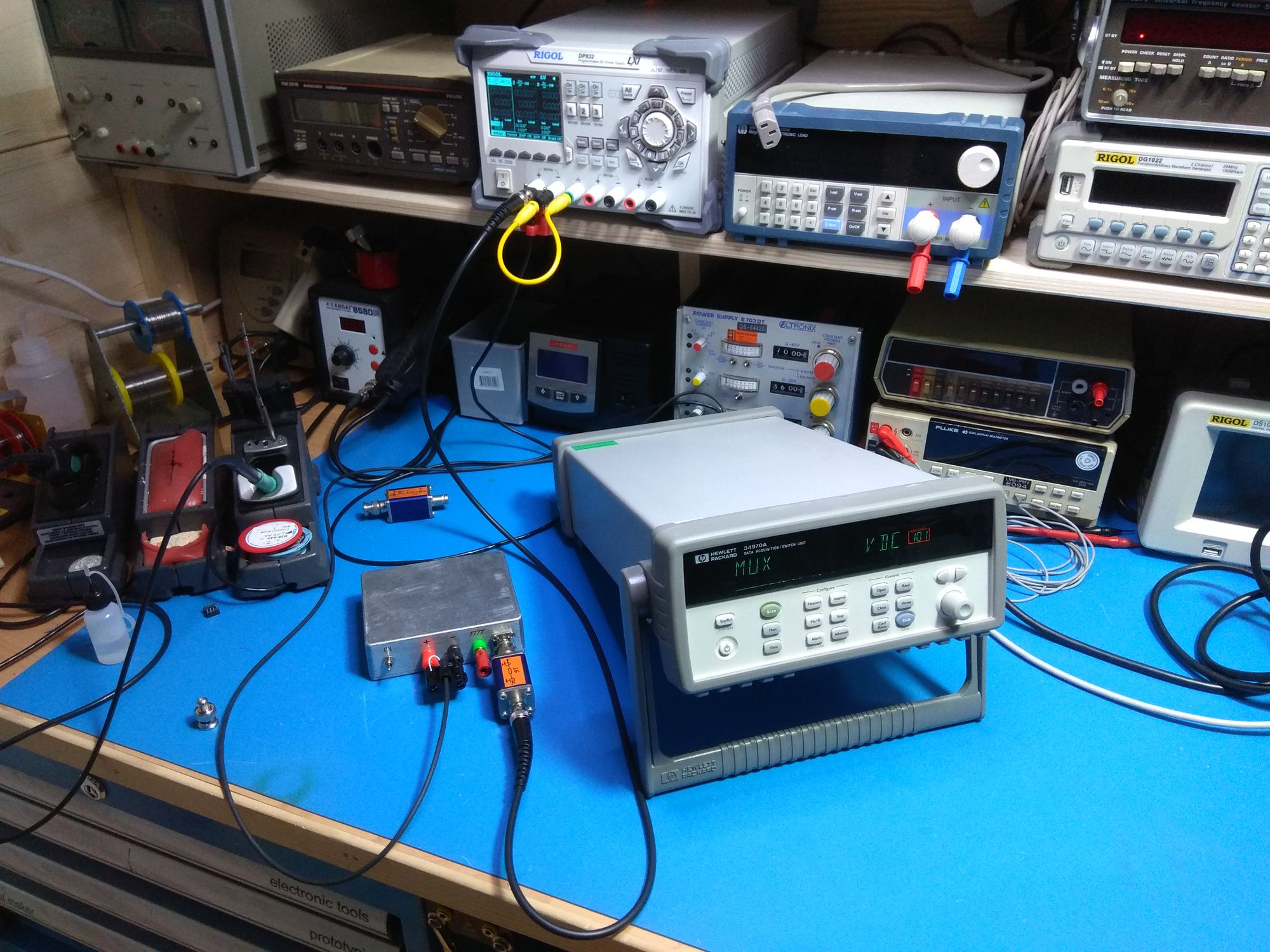
For the tests I made the two boxes in the photo. One is a 1k - 1Ohm voltage divider and the other a 1 GOhm resistor.
If the picoammeter works properly, whatever voltage is fed through the 1GOhm box, should be measured to the output.
The voltage divider is used as a mV power supply (converts V to mV).
1) Step response
I am feeding to the picoammeter 4V through the 1GOhm resistor box.
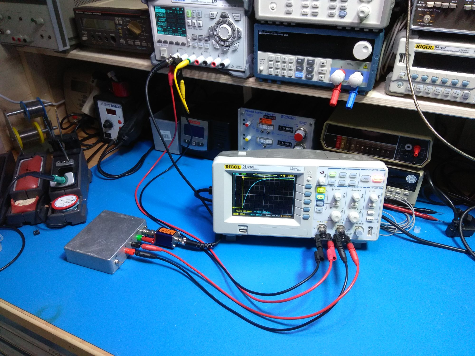
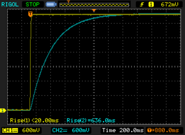
As expected from the values of the resistor and capacitor the bandwidth of the picoammeter is small. With a rise time of 636ms its bandwidth should be about 0.5Hz.
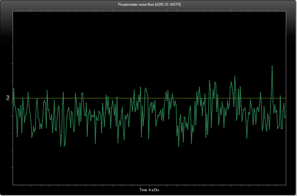
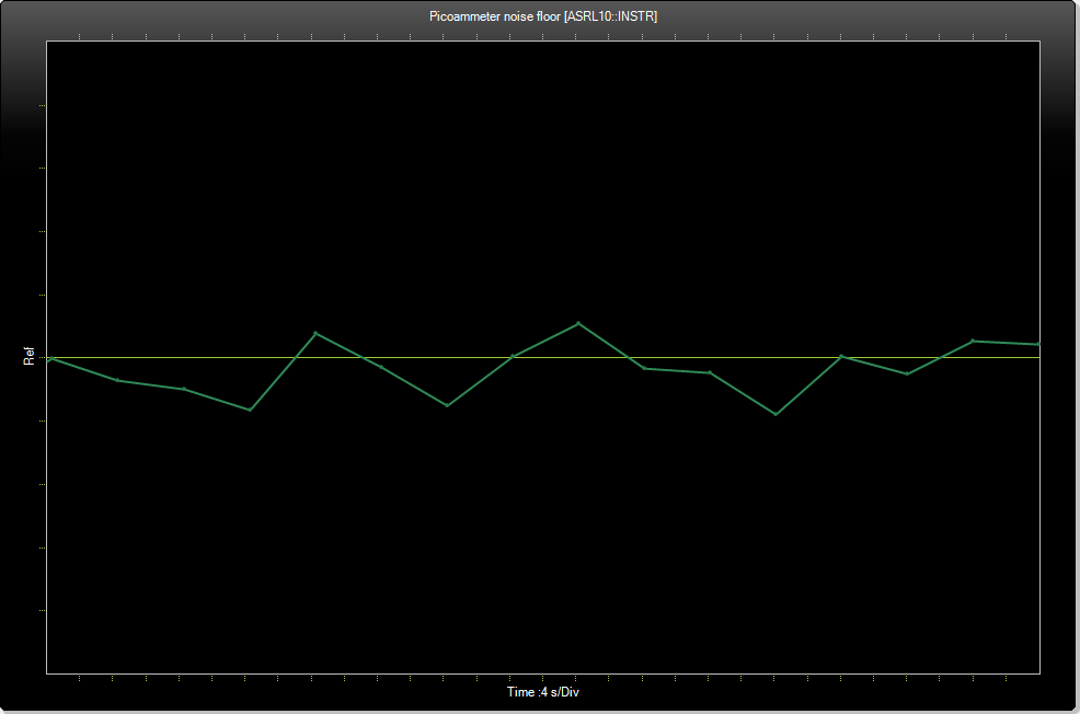
2) Noise
To measure the noise floor of the picoammeter I covered the input BNC with a BNC cup. I also turned off my crappy LED lights.
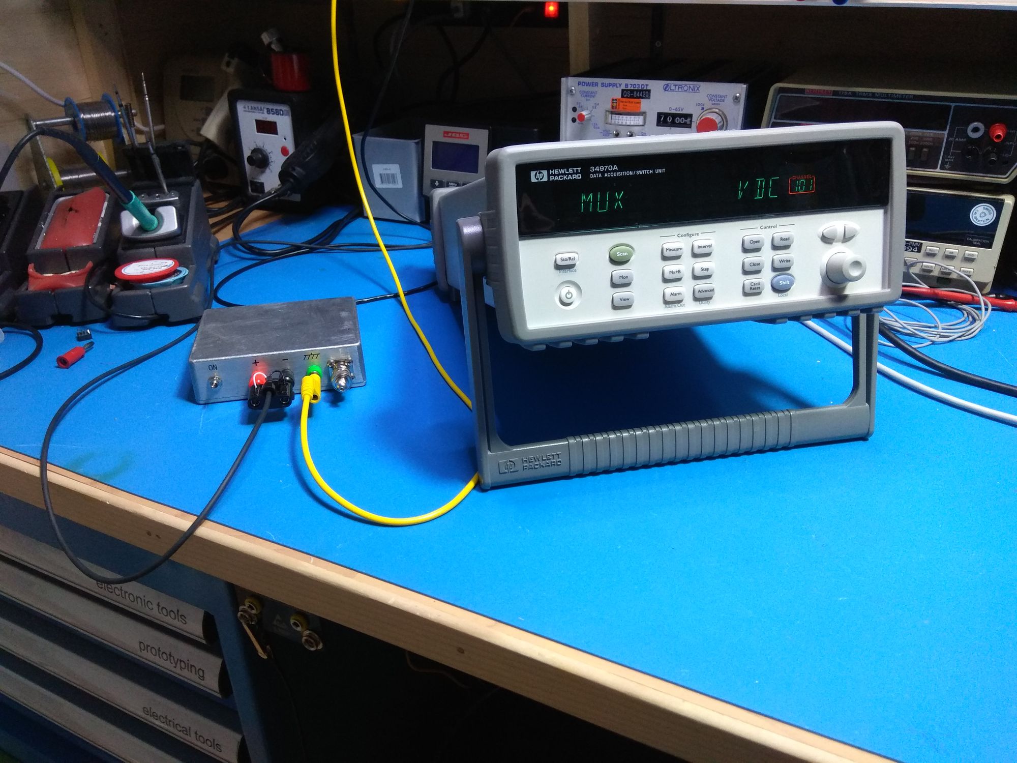
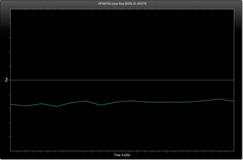
Just for good measure this is the noise floor of the HP34970A
3) Linearity
To test the linearity of the picoammeter I am feeding a 0 to 4V ramp and a 0 to -4V ramp from my DP832 through an 1 GOhm resistor. So in principle I should see the same voltage at it's output. This corresonds to the full ±4nA scale of the instrument.
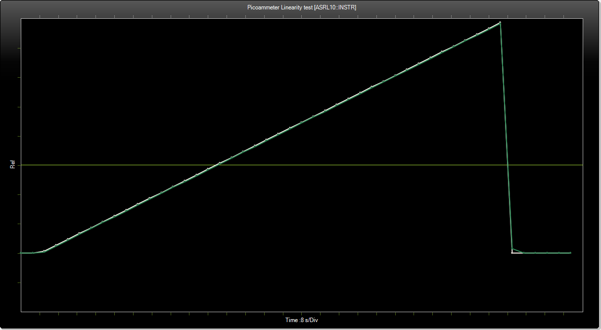
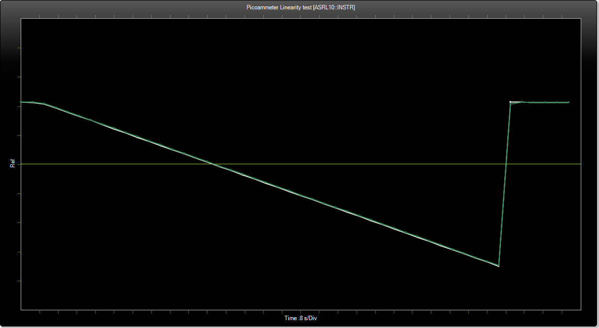
Here is the python code for the DP832 that makes the ramp. See also this article.
4) Resolution
Now lets see what is the finest measurement possible. For this test I am feeding a 0 to 100mV ramp through the voltage divider box and the 1GOhm resistor. This corresponds to 0 to 100fA.
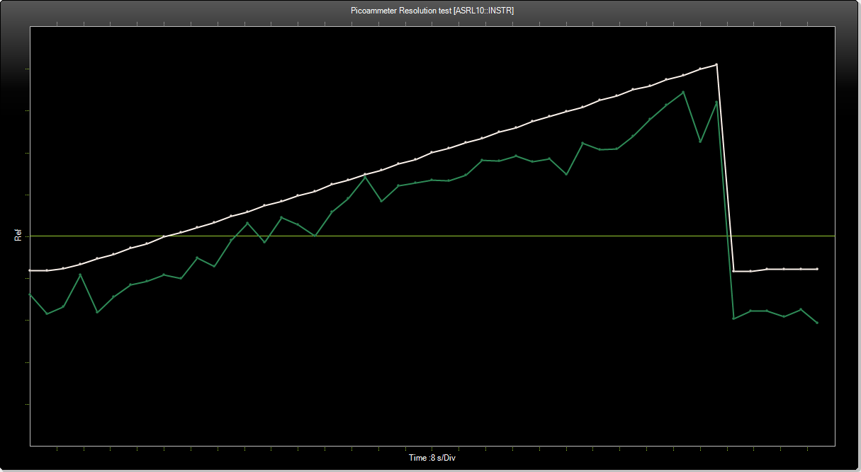
20μV correspond to 20 fA. I would say that the resolution of the instrument is ±20fA.