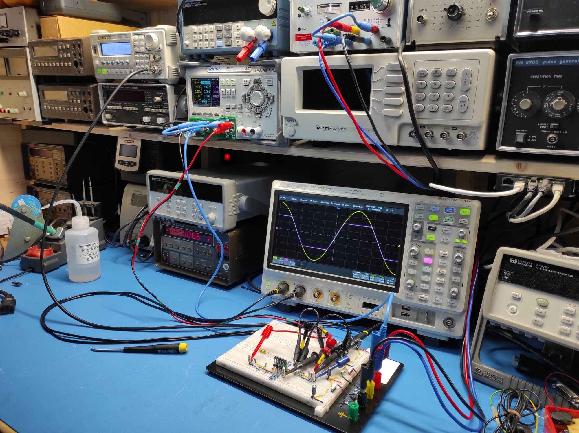
To test my clipper design I have built the following circuit:
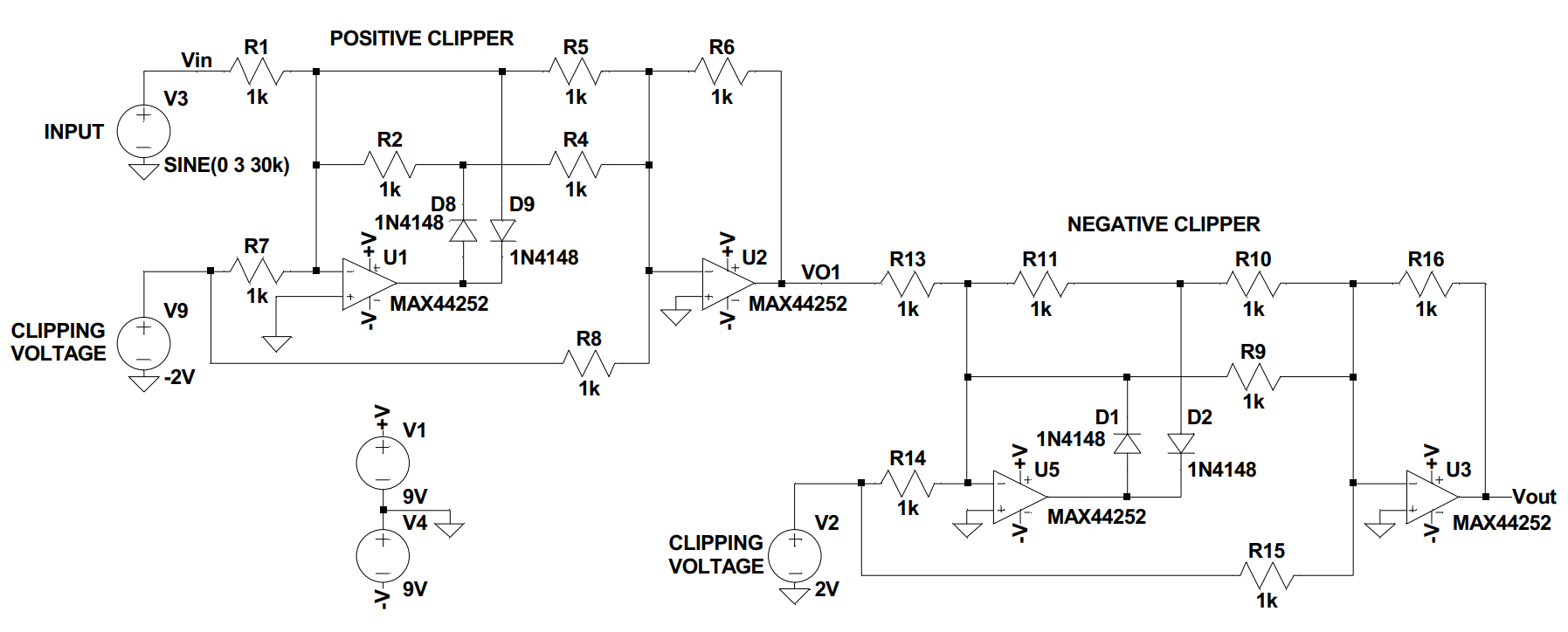
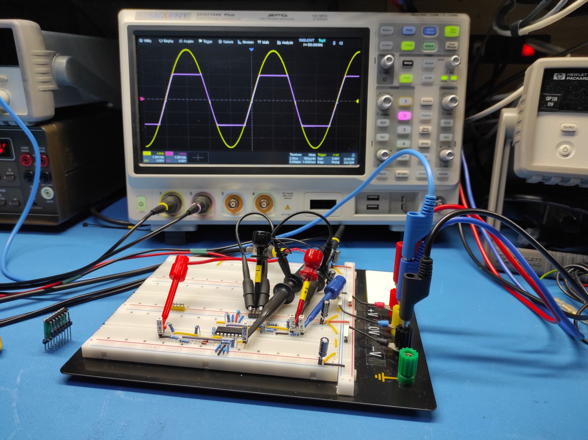
As you can see it a positive clipper followed by a negative clipper. The op amp used is the MAX44252 from TI. It was the fastest 4-ply op amp in my lab. I wish I had some LT6015s that Analog Devices used in their circuit. This is my test setup:
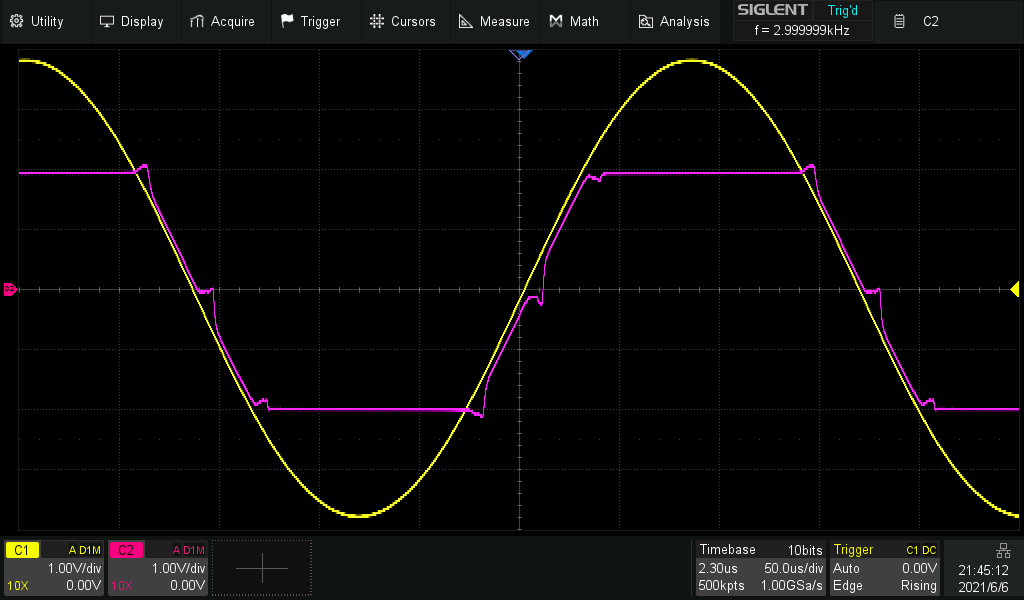
Let's go for the jugular first. How does it compare to AD's circuit at 30kH?
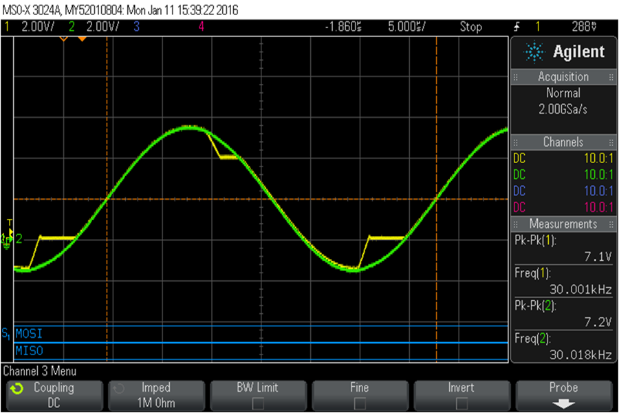

I think it is doing better :). Let me zoom the clipping in to be more legible.
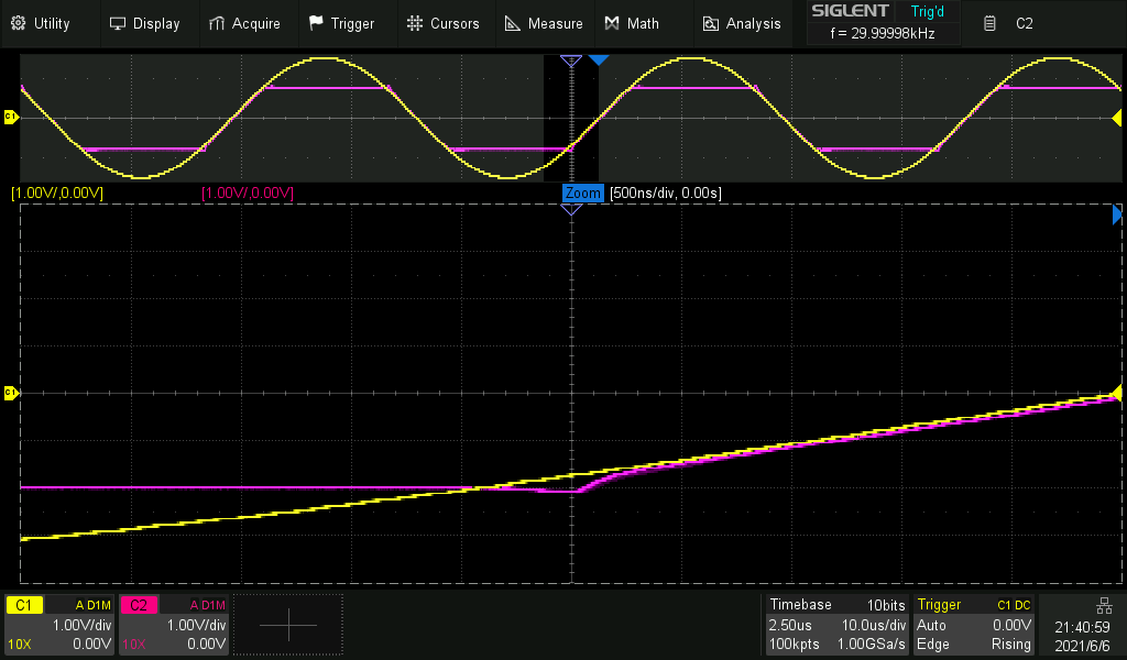
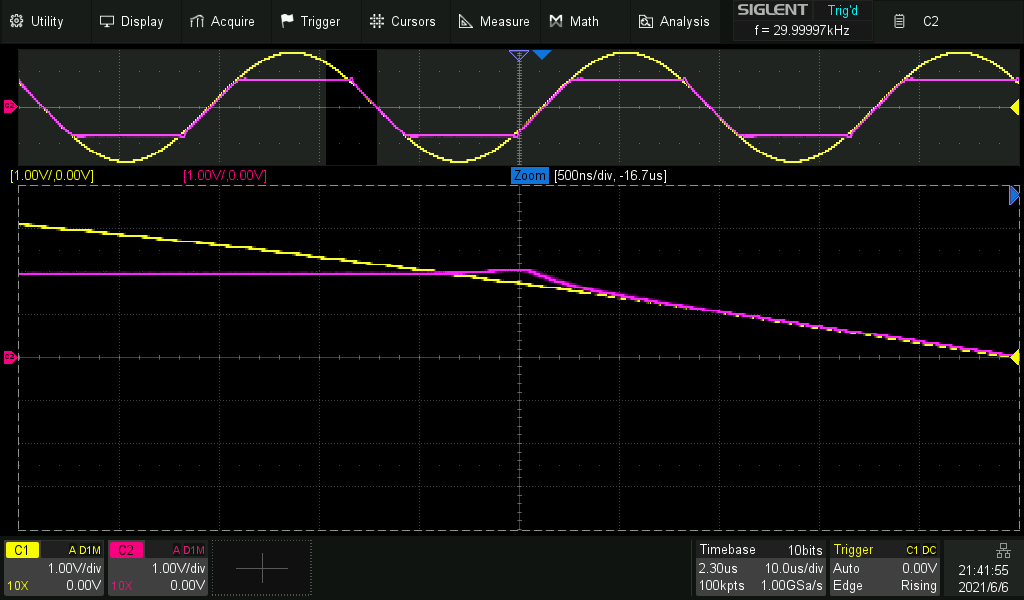
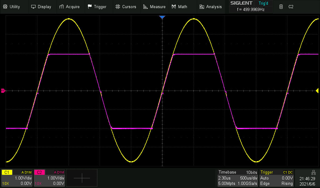
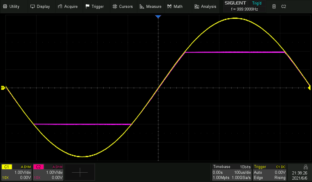
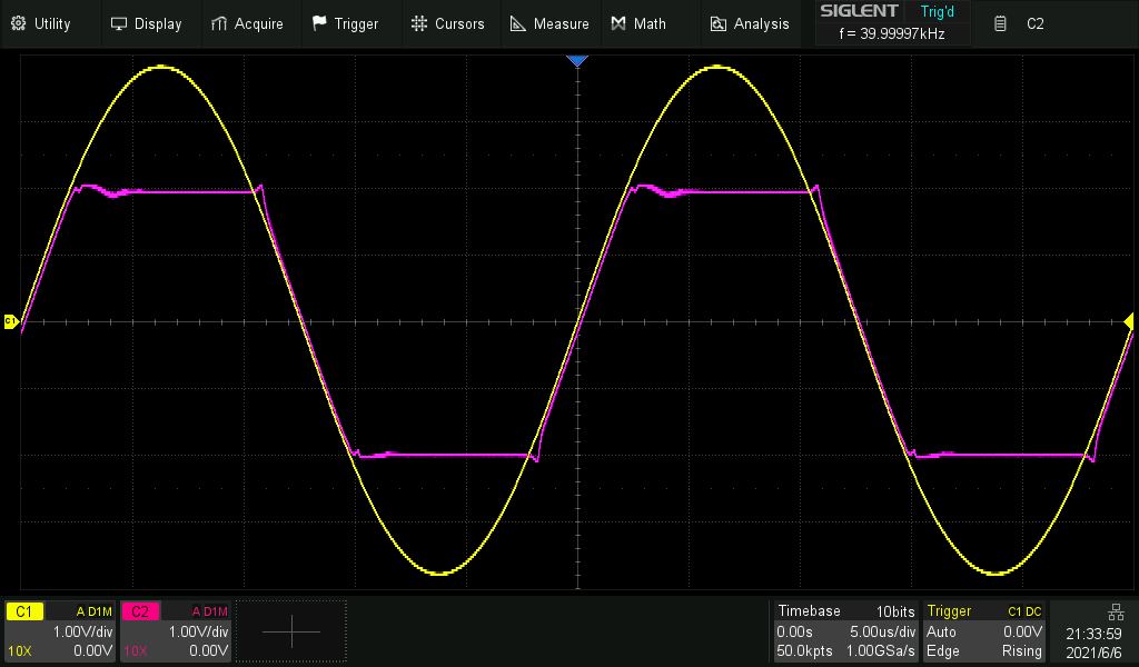
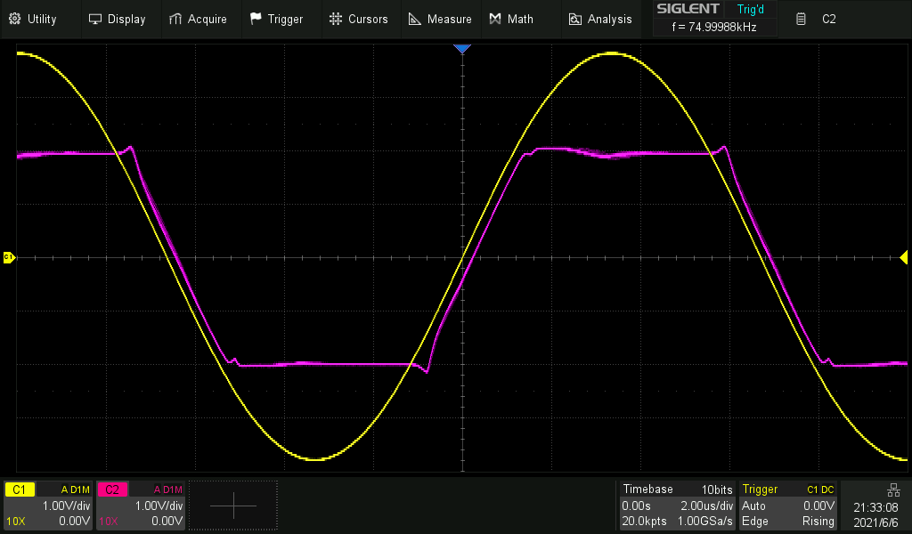
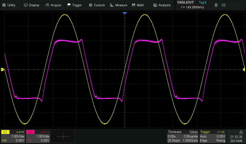
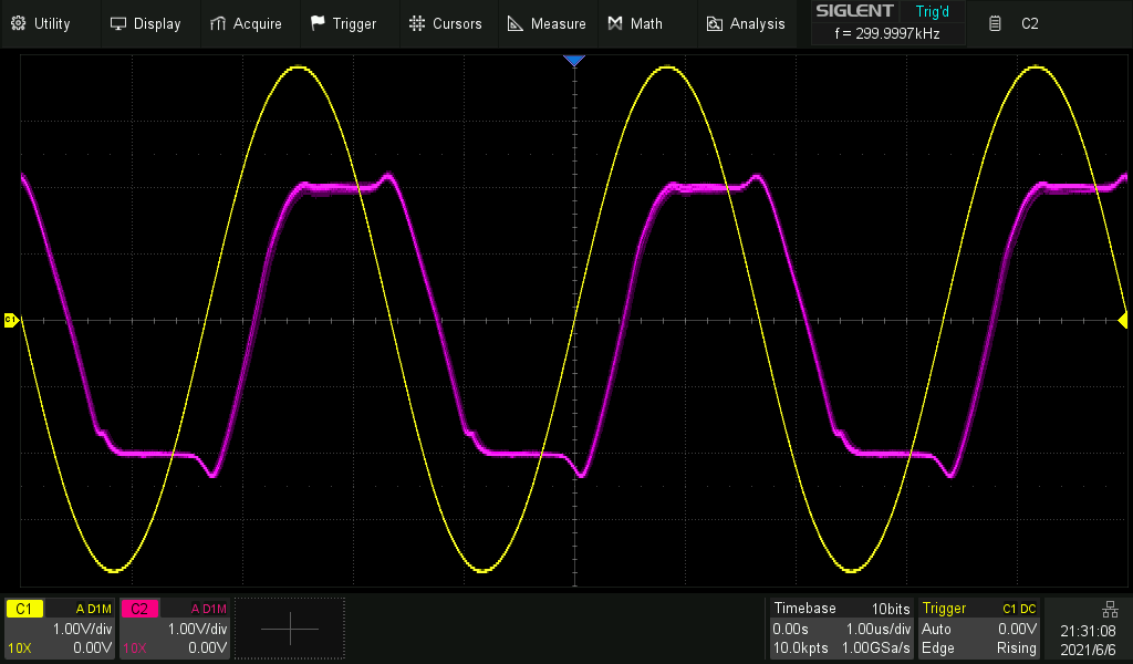
Now let's test it on different frequencies. The input signal is 8Vpp and the clipping happens at +2V and -2V.

Just for fun I changed the op amp with a really slow LM324.