References/links:
- LTSpice files (github)
For no particular reason I was looking at clipper circuits. If you search google for "clipper circuit op amp" you get variations of this circuit:
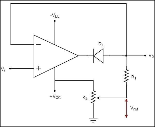
This circuit works like a voltage follower when D1 conducts (i.e. Vi < Vref) and outputs Vref when not (i.e. Vi > Vref). For any practical application it needs an output buffer too.
Even Analog Devices had this circuit to offer:
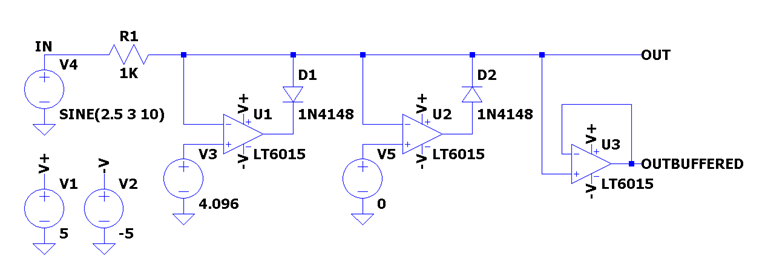
Which cannot hold its own at 30kHz and also needs a special kind of op amp (when the diodes are not conducting the inverting and non inverting inputs are not at the same potential. The op amp should be able to tolerate this. See Analog Device's article for more details.).
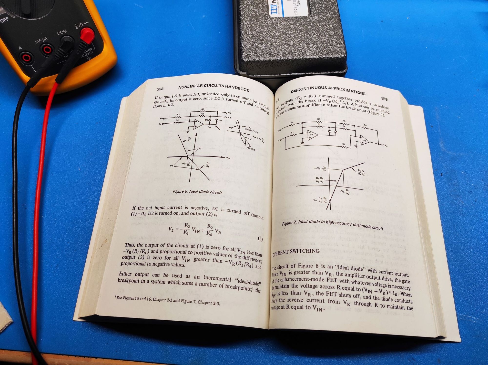
I mean WTF? Are we so far gone that we call this precision? What has this world come to? Sunk deep into depression about humanity's prospects I turned to one of my prayer books for solace. And, lo and behold, the answer was revealed to me on page 359 of the treasure trove of arcane wisdom called nonlinear circuits handbook. Quite ironically by Analog Devices.
A better solution
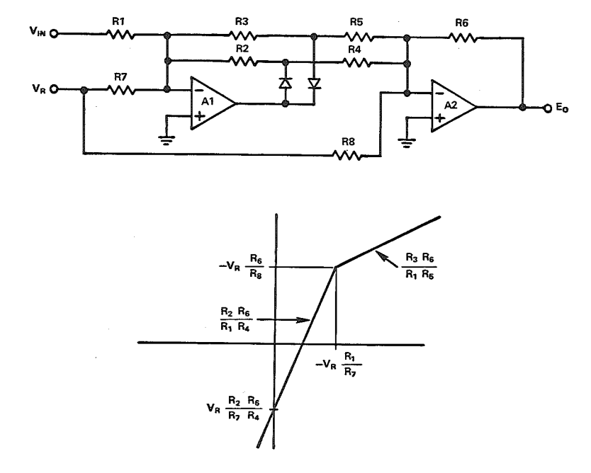
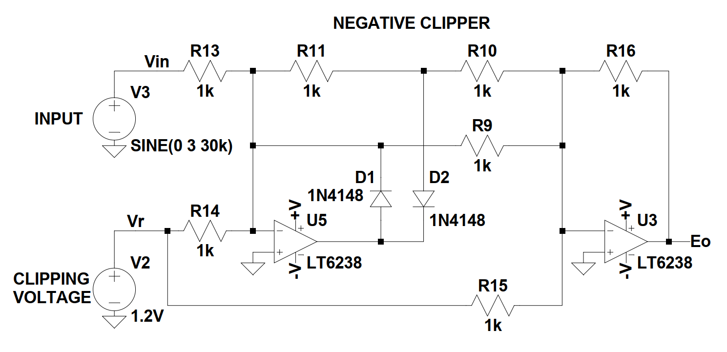
This circuit can be easily modified to either a positive or a negative clipper. If we set R3 to 0Ω and all other resistors to the same value the break point's X and Y coordinates become (-VR, -VR), the slope before -VR 1 and after -VR 0 (X-axis is VIN and Y-axis EO). That is a positive clipper. For a negative one we set R2 to 0Ω and all others the same.
I will now attempt to explain the circuit:
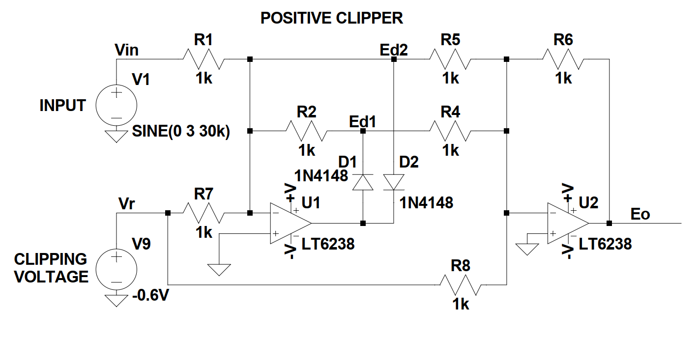
- Since all resistors have the same value U1 and U2 work as unity gain inverting amplifiers.
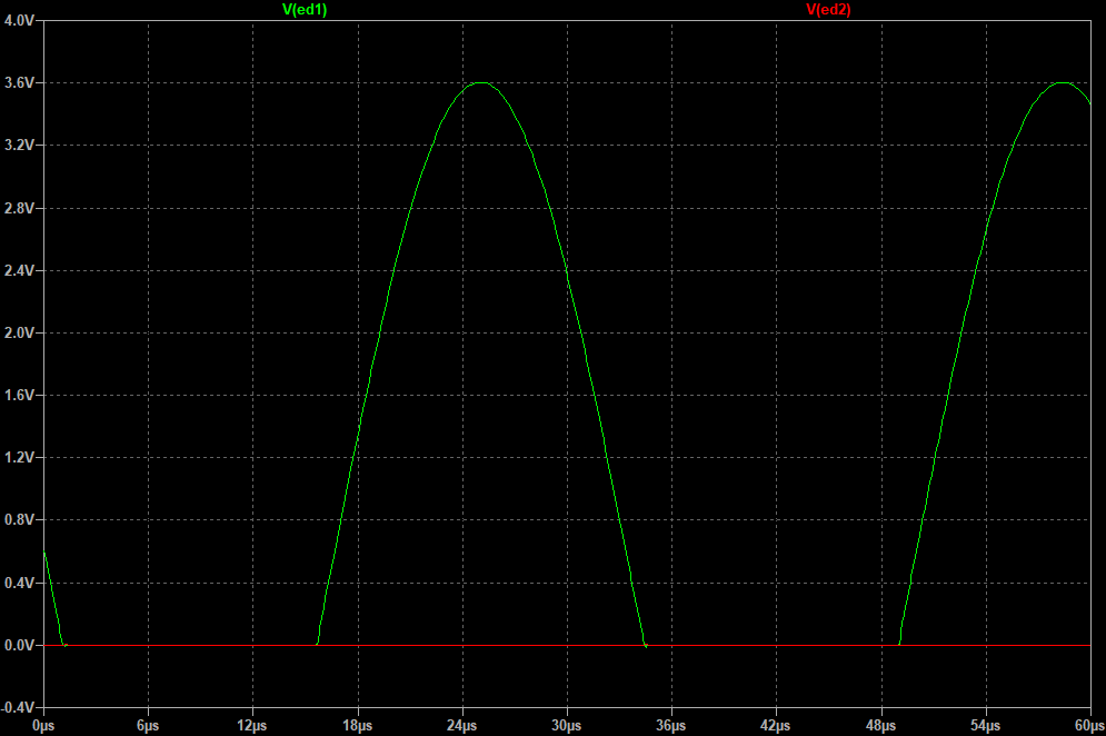
- When the sum \(Vin+Vr < 0\) then D1 conducts and: $$Ed1 = -(Vin+Vr)$$ $$Ed2 = 0$$
- When the sum \(Vin+Vr > 0\) then D2 conducts and: $$Ed1 = 0$$ $$Ed2 = 0$$
- Op amp U2 sums Ed1, Ed2 and Vr and inverts them: $$Eo = -(Ed1+Ed2+Vr)$$
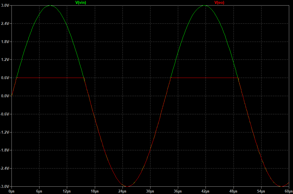
- So when \(Vin > -Vr\) $$Eo = - (0+0-0.6) = 0.6V$$
- And when \(Vin < -Vr\) $$Eo = - ( -(Vin-0.6)+0-0.6) = Vin$$
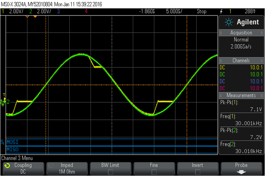
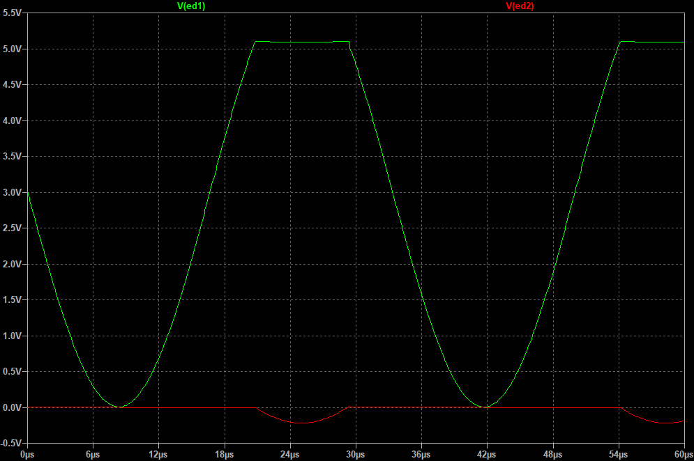
One drawback of this circuit is that you need to allow enough headroom for Ed1 or else it will clip at the op amp's positive rail and distort the output signal. Here's what happens when Er = -3V (the voltage rails of the op amp are +6V and -6V):
A negative clipper would look like this: