A few weeks ago my HP 35665A stopped working. The power supply blew. The problem with these power supplies is that they are very hard to find. Even if you are lucky enough to spot one in eBay they are going to ask an arm and a leg for it. So repair may be the only viable option.
So you decided to give it a go and repair it. You will soon find out that no service manual or schematics are available. Despair not though. The parts are all through-hole and mostly still available. The boards is a 2-layer PCB that is easy to trace and probe. I am documenting this repair hopping to help the unfortunate souls that have embarked on a similar journey.
Some warnings before we begin
High voltage will kill you (mainly because it can stop your heart). If you mess around with mains voltages without knowing what you're doing you are eligible for a Darwin Award (Congratulations?).
If available use an isolation transformer. At minimum work behind a residual current circuit breaker.
Do not connect your oscilloscope directly to this circuit. You will burn it. Use a high voltage differential probe instead.
The problem
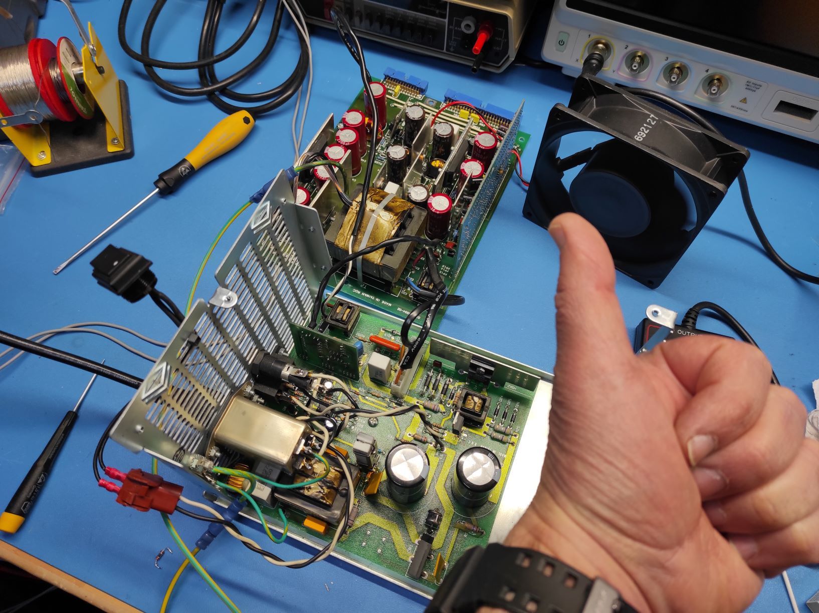
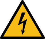
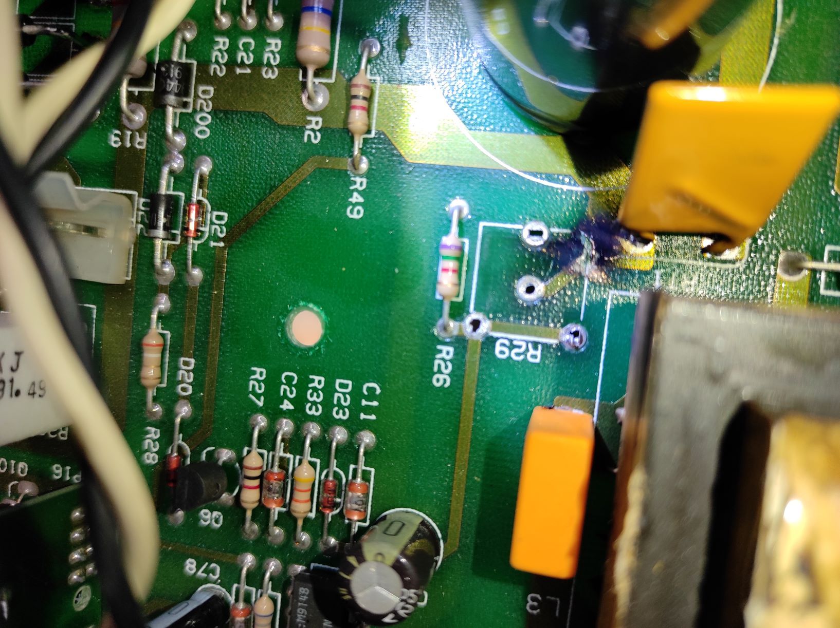
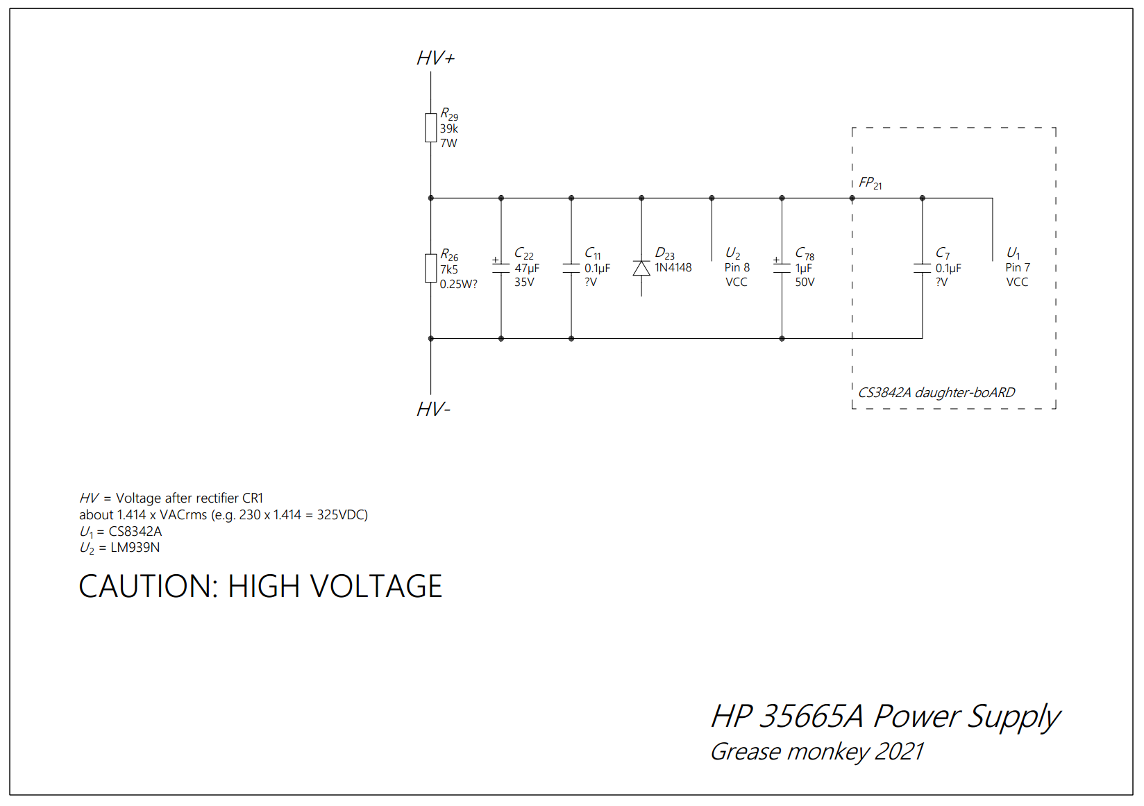
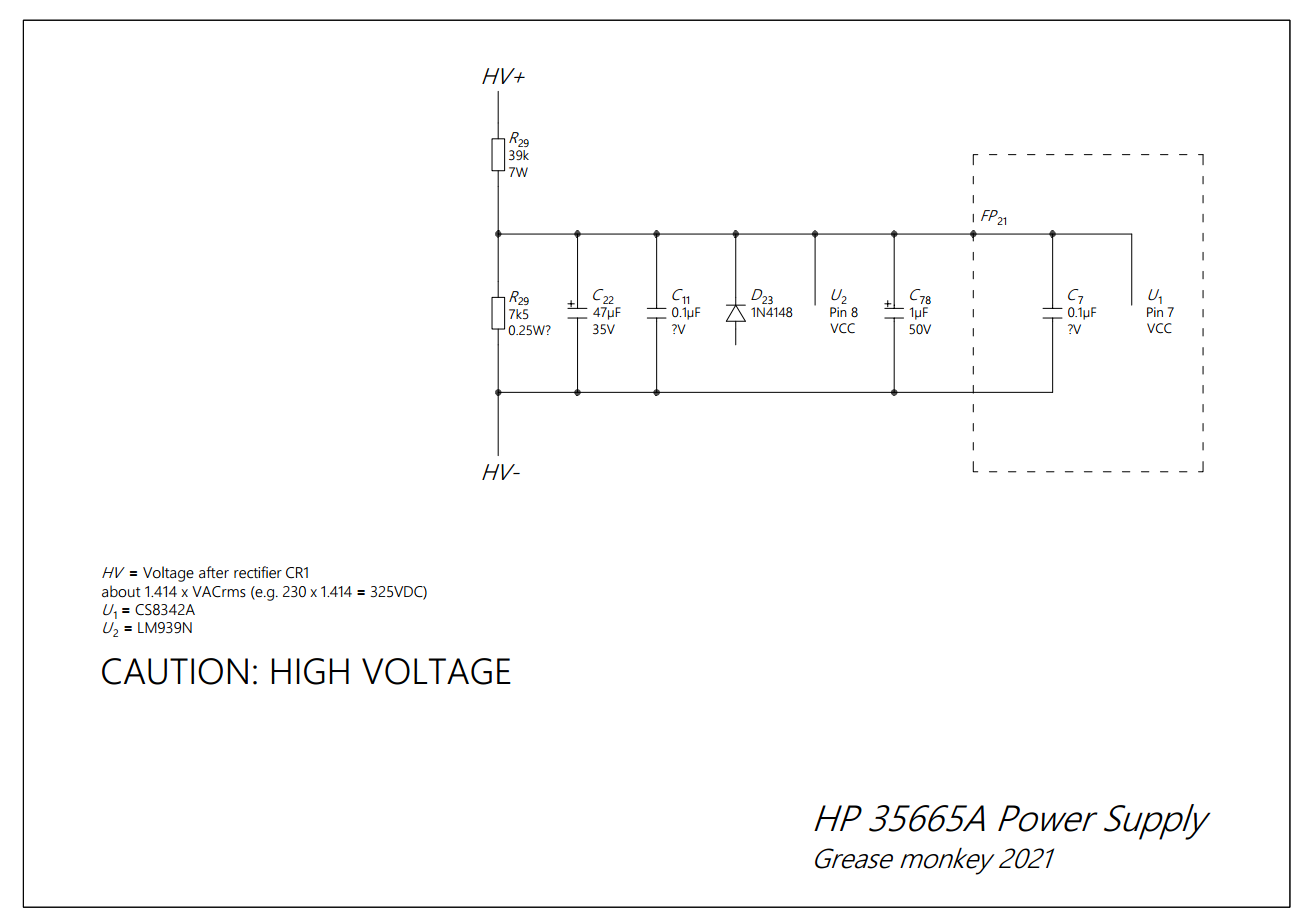
The power supply [PSU] has two boards. The board on top handles the isolated side. The board on the bottom handles the mains side. It contains the EMI, PFC and current inrush circuits, the rectification and the drive of the transformer's primary coil. The drive consists of a mosfet (\(Q_5\)) driving a BJT (\(Q_4\)).After a quick inspection I located the first problem. The case of \(R_{29}\) short-circuited to the PCB trace under it (effectively short-circuiting \(R_{29}\)).
| Designator | Type | Digikey ref |
|---|---|---|
| D23 | 1N4148 | 1N4148FSCT-ND |
| Q5 | STP16NF06 | 497-2766-5-ND |
| Q8 | PN2222 | PN2222ATACT-ND |
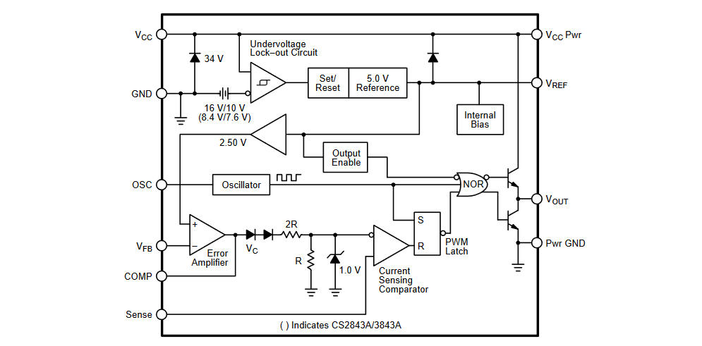
I also noticed that the voltage on pin 7 of the CS3842A was only 9V. CS3842A does not start with such a low voltage. Check the Under-voltage Lock-out Circuit in the diagram below.
I decided not to bother any further finding if anything else is faulty so I changed the following components too.
| Designator | Type | Digikey ref |
|---|---|---|
| U1 | UC3842AN | 296-11280-5-ND |
| U2 | LM393N/NOPB | LM393NNS/NOPB-ND |
| C11, C7 | 0.1μF Cer. 100V | 478-4855-ND |
| C22 | 63μF 63V | - |
| C22 | 1μF 100V | - |
BTW the postmortem of the capacitors showed that they survived the over-voltage just fine. But I changed them anyway. It is also a good idea to install sockets for the two ICs. You never know when the next time will be.
In the end...
The moral of the story... do not give up. In fact I bought this analyzer cheap about a year ago as faulty (also from the PSU). And that repair was very easy. It was the three 5.3V zener diodes.