References/links:
Don't you just love it when a $500 recently calibrated current clamp appears in a dumpster? I do.
Repair
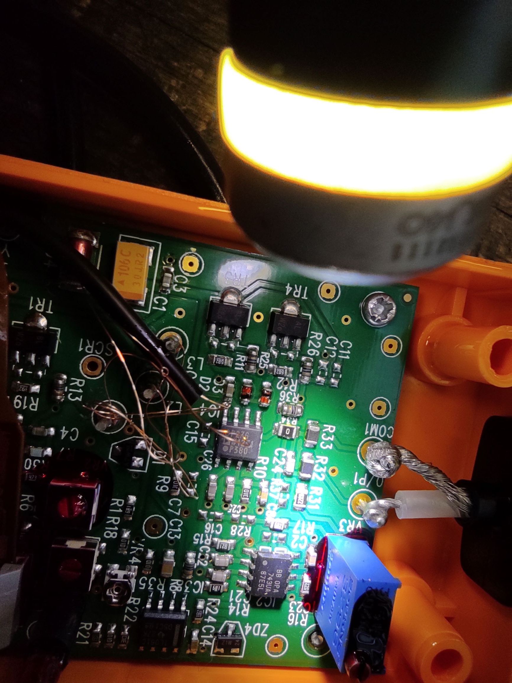
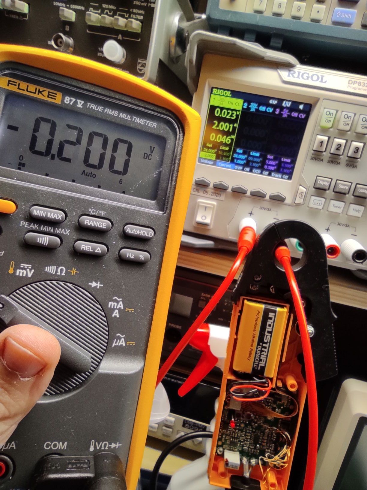
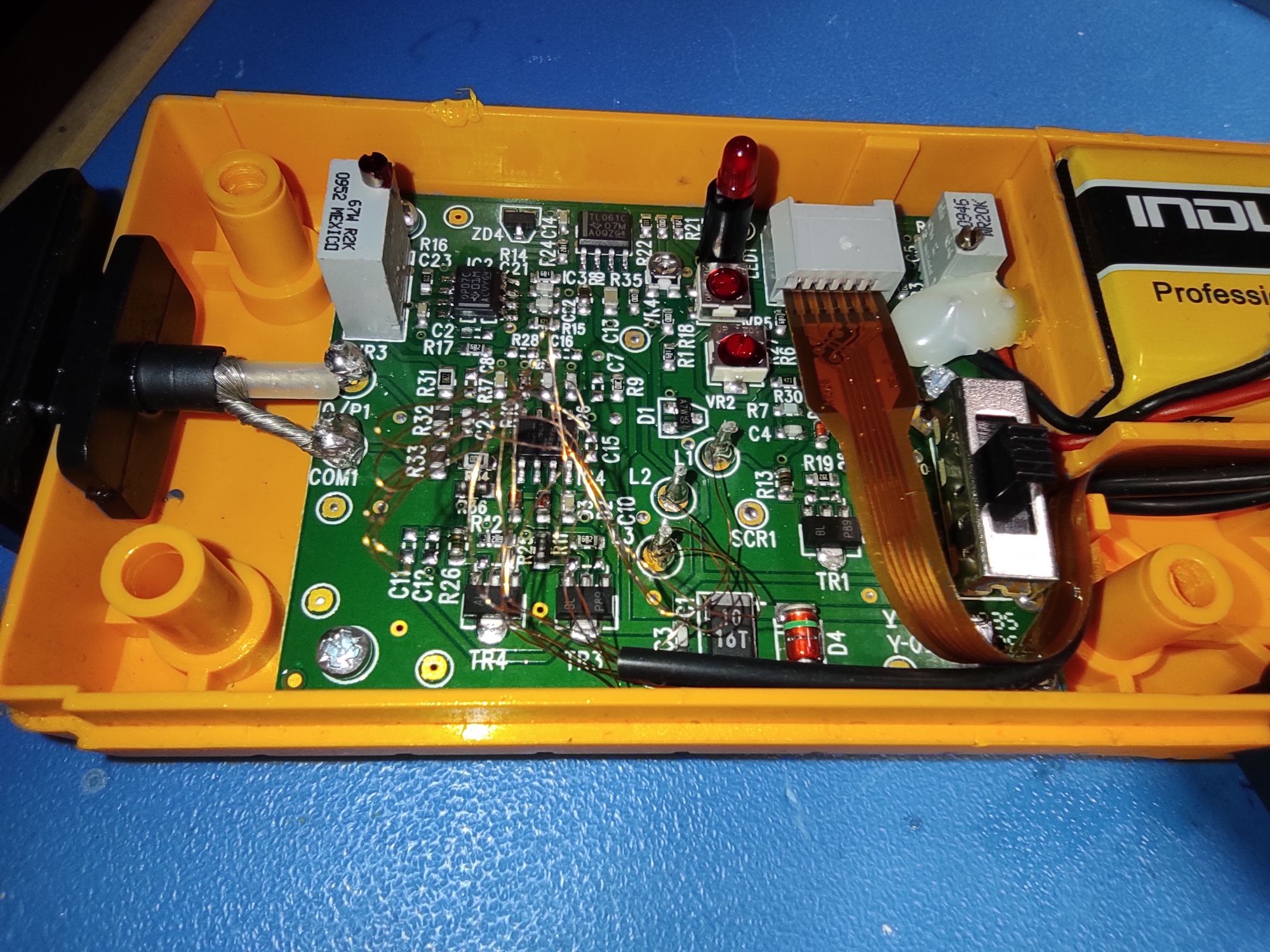
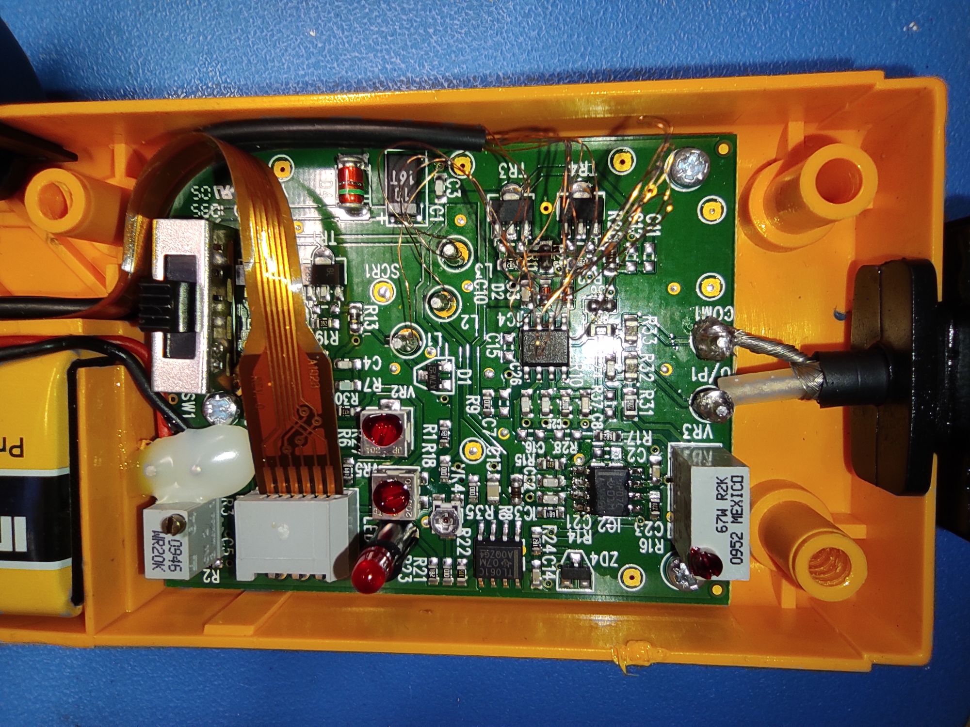
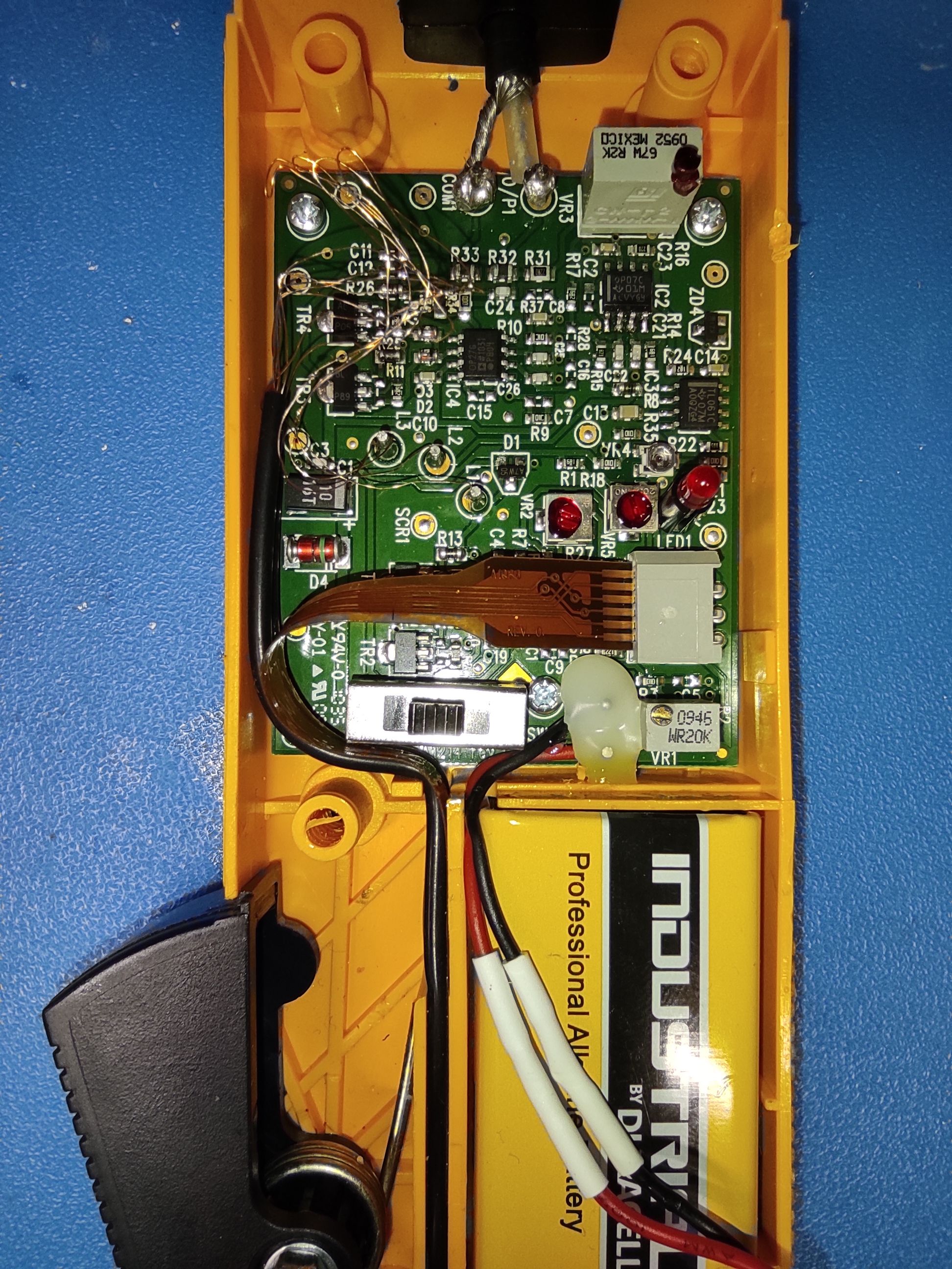
Sometimes, when I repair things, I am not sure if like it when the problem is obvious. This was certainly one of those cases. The output op amp had a hole on it. I guess someone plugged it where it does not belong...
It is so nice that Fluke doesn't laser out the part numbers. Unfortunately the part number of the op amp was written on the spot that the magic smoke escaped. Since I could not find any service manuals or any hi res photos of the i30's PCB, I had to guess the op amp type.
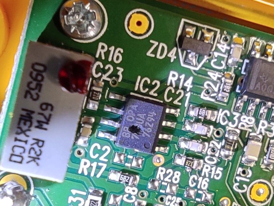
We know the following:
- BB means "Burr-Brown" (currently Texas Instruments)
- The part number is OPA7XXUA
- It is a SOIC-8 package
- It is a single op amp device
- The supply voltage (across pins 4 (V-) and 7 (V+)) is about 8.7V (one diode drop from the 9V battery voltage). Just for good measure I measured the supply voltages of the other op amps too and they were the same.
A quick search on Digi-Key with the above constraints gave me the following options. OPA703UA, OPA704UA, OPA705UA, OPA743UA. The good thing is that all of them have the same pinout and similar supply voltages. This makes them compatible.
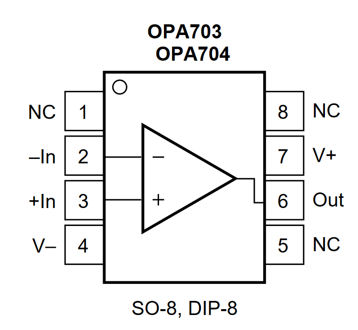
The only op amp with a compatible package and footprint in my lab was the venerable OP07. An oldie but a goodie. So I changed it and...
Is the OP07 adequate?
The OP07 I soldered is the OP07CDR. Lets see if it cuts the mustard:
- The Input Bias Current of the OP07 is 1.8nA. Since this is only the output amp and it is fed by other amplifiers it should not be a problem.
- The Unity Gain Bandwidth is 600kHz (400kHz minimum). The op amp is connected as non-inverting amplifier with G=10 (I didn't reverse engineer the board, I just measured the input and output). To cover the 20kHz 0.5dB (~90%) loss it is perhaps barely enough.
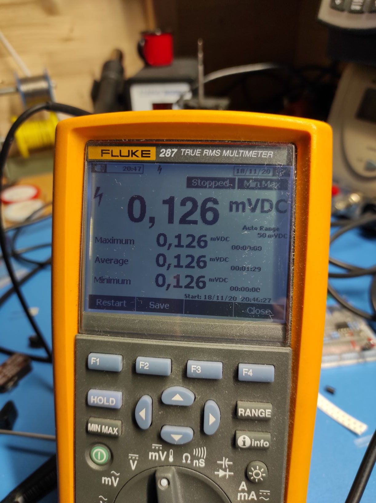
- Its input voltage offset is 60μV (150μV max). And it is not possible to trim the offset in this board (the offset pins are not connected, they just go to C2 which is not populated). So I measured the offset between IN- and IN+. It is 126μV and it does not depend on the current passing though the clamp. This offset voltage will introduce an error of 1,3mV (or 13mA) to the measurement. Since the accuracy is 1% of reading ±2mA and the resolution ±1mA this is not acceptable.
Selecting another op amp
The op amp should have the following specs:
- Input offset voltage < 10μV. 1mA translates to 100μV so let's make it an order of magnitude better.
- Supply voltage at least 10V since we have a 9V battery.
- SOIC-8 package.
- Unity Gain Bandwidth > 1MHz.
Searching Digi-Key for an op amp with the above features (and sorting by price of course) I decided on the OPA189.
The input offset voltage is 0.4μV typical (4μV max). It has plenty of bandwidth (flat response at G=+10 up to 500kHz). The input bias current is 70pA and works from 4.5 to 36V (single supply). Finally it is moderately priced at CHF 2.27 (quantity = 1).
I will update this post when the op amp arrives.
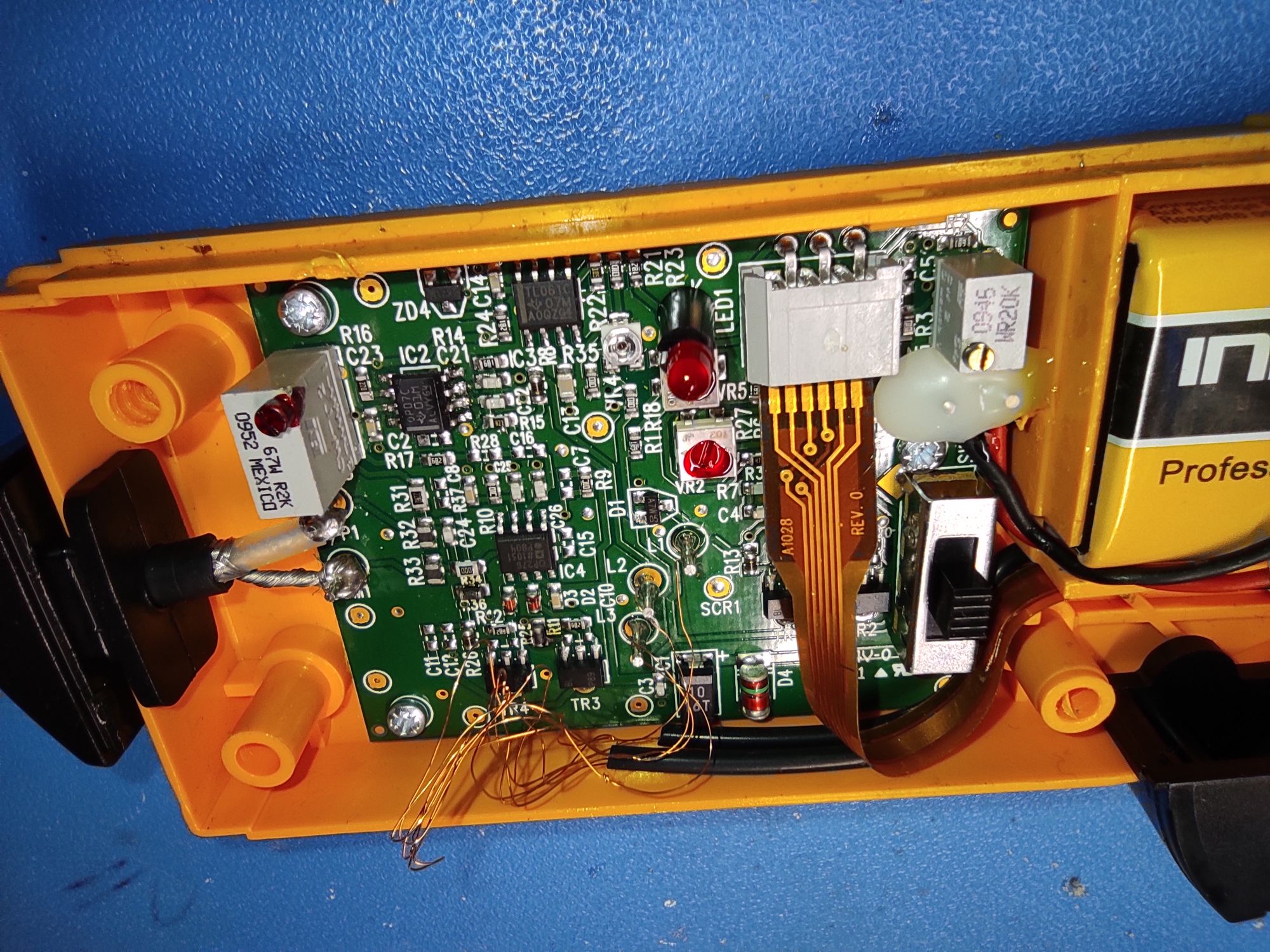
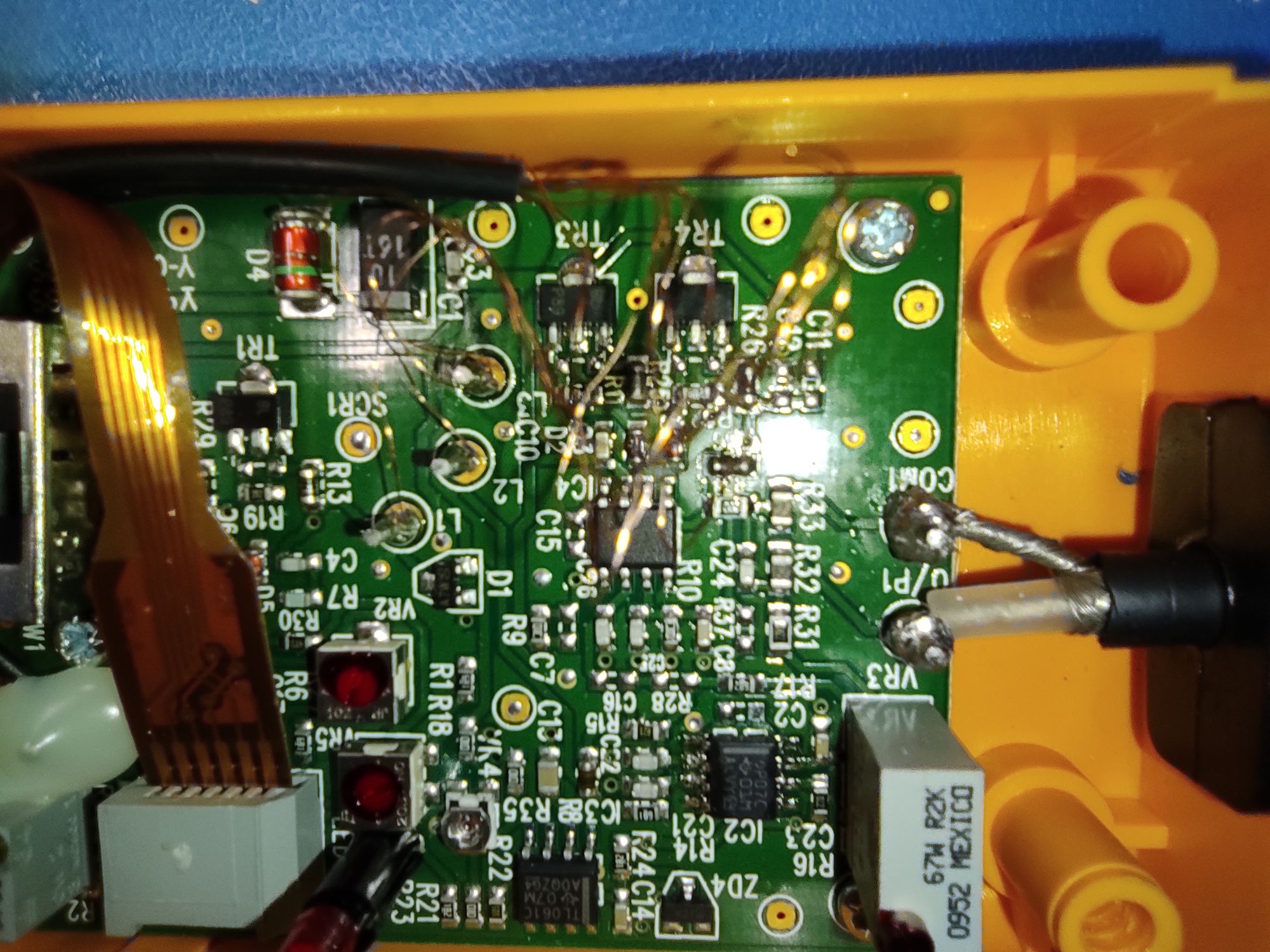
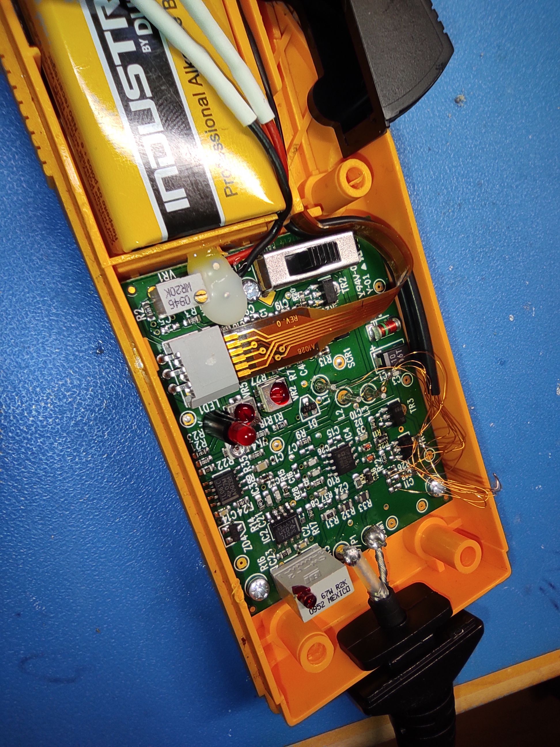
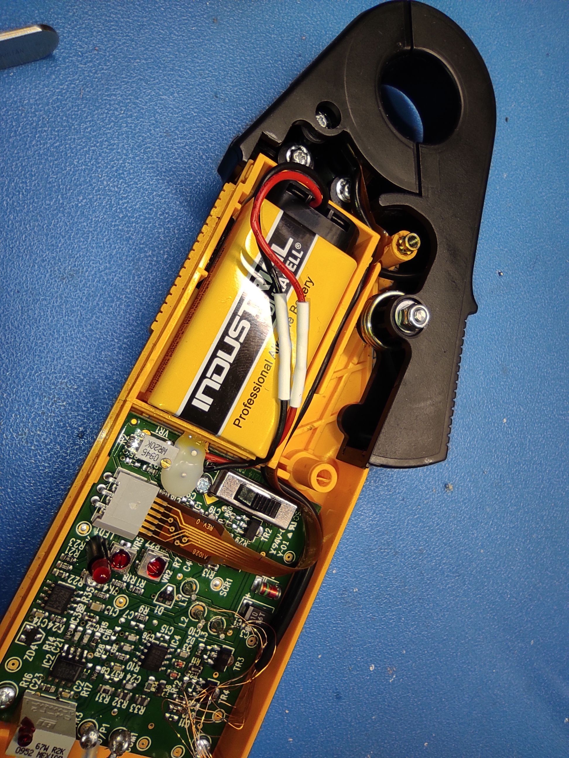
Teardown
Here are some photos from the insides of the clamp.
Update 17.02.2021
I repaired another i30. The original output op amp is the OPA743.